Drawing
Drawing of a detail
Drawing - a document containing a contour image products and other data necessary for both the manufacture, control and identification of the product, and for operations with the document itself.
Drawing is one of the types of design documents and, on the other hand, is one of the types of graphic models products.
The basic requirements for the implementation of the drawings are set out in GOST 2.109-73.
Sheet Formats
International standard sheet sizes, ISO 216 (GOST 2.301-68), is built on the basis of the German standard sheet sizes DIN 476. In the standard ISO the ratio of the width to the length of sheets of different formats is the same, and is, Or about 1: 1.4142. The basic format of the sheet is A0, the area of which is 1 m². Each of the following formats of sheets A1, A2, A3, etc., has half the area of the previous one. These formats for GOST 2.302-68 have the name "basic formats".
Basic format - the format of the design document preferred, the sides of which are 1189 × 841 mm (A0) or obtained by successively dividing it into two equal parts parallel to the smaller side up to the format 297 × 210 mm (A4).
Additional format - the format of the design document, which is formed by increasing the smaller side of any basic format by an amount multiple of its size.
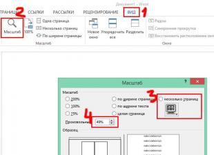
Scope
The image of the object in the drawing can be made in full size, reduced or enlarged. The ratio of all linear dimensions of the image of the object in the drawing to their natural value is called scale.
GOST 2.302-68 sets the following series of scales of images in the drawings:
- scale reduction - 1: 2; 1: 2.5; 1: 4; 1: 5; 1:10; 1:15; 1:20; 1:25; 1:40; 1:75; 1: 100, 1: 200;
- the natural value is 1: 1;
- scale of increase - 2: 1; 2.5: 1; 4: 1; 5: 1; 10: 1; 40: 1; 50: 1; 100: 1.
Lines
The main elements of any drawing are lines. Depending on their purpose, they have the appropriate type and thickness. The image of objects in the drawing is a combination of different types of lines.
Line types, their purpose and thickness are set GOST 2.303-68 (ISO 128). The solid thick main line is taken as the original one. The thickness of it S should be selected in the range from 0.5 to 1.4 mm. It is selected depending on the size and complexity of the image, the layout of the sheet and the purpose of the drawing. Based on the thickness of the solid thick main line, the thickness of the other lines is selected, provided that for each type of line within the same drawing in all images, it will be the same.
Types, thicknesses and designations of lines for GOST 2.303-68:
| Name | Thickness relative to the main line | Main purpose |
|---|---|---|
| Solid thick | S | Lines of the visible contour. Transition lines are visible. Lines of the contour of the section (taken out and included in the composition of the section). |
| Thin solid | From S / 3 before S / 2 | Lines of contour of superimposed cross-section. Lines dimensional and remote. Hatching lines. Lines-callouts. Shelves of lines-callouts and underlining of inscriptions. Lines of limiting remote elements on views, sections and sections. Imaginary transfer lines. Traces of planes, lines of construction of characteristic points under special constructions. |
| Solid wavy | From S / 3 before S / 2 | Lines of precipice. Lines of demarcation of a species and a section. |
| Dashed | From S / 3 before S / 2 | Lines of the invisible contour. The transition lines are invisible. |
| Bar-dashed thin | From S / 3 before S / 2 | Axial and centric lines. Section lines that are symmetry axes for superimposed or rendered sections. |
| Bar-dotted thickened | From S / 3 to 2 / 3S | Lines denoting surfaces to be heat treated or coated. Lines for the image of elements located in front of the cutting plane. |
| Open-ended | From S to 1.5 S | Lines of sections. |
| Solid thin with a break | From S / 3 before S / 2 | Long lines of precipice. |
| Bar-dashed with two dots thin | From S / 3 before S / 2 | Bend lines on the sweep. Lines for the image of parts of products in extreme or intermediate positions. Lines for a scan image combined with a view. |
Drawing
Schedule for work
Government building plan
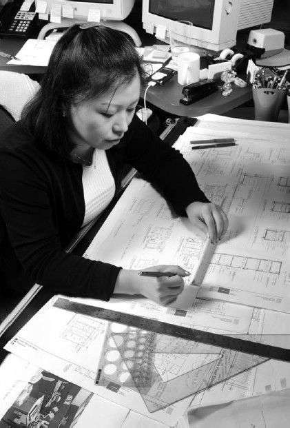
When objects are depicted using drawing techniques, they do not rely on one eye and the fidelity of the hand, but use different auxiliary tools. But the drawing requires an exact reproduction of the dimensions of the object, in a certain scale , as a result of which the perspective image is used very rarely (since it distorts the dimensions of parts) and is replaced projections , according to the rules descriptive geometry . With the development of applications graphic Statics with the help of drawing steel quickly and easily solve a lot of numerical problems encountered in the design of structures and machines and requiring complex of algebraic calculations.
Under the name "geometric drawing" means a special preparatory subject of the program of primary technical schools: in order to begin studying the art of drawing students are shown methods of using drawing tools and force to solve on paper different geometric problems. Beginning with the really necessary ones, like holding parallel and perpendicular lines, dividing lines and angles into equal parts, constructing figures on different scales reach the solution of rather complex particular problems and the construction of different flat curves and regular patterns chosen only for the purpose of "filling the hand" and to achieve some degree of geometric "development." Then they turn to "projective drawing": practical study of descriptive geometry and different systems of projections based on it. These scientific principles of drafting are developed further in accordance with specialties that require a variety of results, achieved by special techniques and skills. Drawing geographical and topographic maps , situational and boundary plans requires the observance of great accuracy in the size and coloring of conventional colors and techniques. Architectural Drawing uses other symbols and methods, but also requires exact observance of dimensions, since they are determined by using a plan by direct measurement with the help of a compass and scale. In the factory drawings given to the executing workers, for the most part, a more rough execution is allowed, because the main dimensions are usually inscribed, and the drawings themselves are often executed in full size.
In the old days it was customary to carefully trim all engineering, architectural and engineering drawings: draw thin lines, carefully paint and even shade rounded surfaces by blurring carcasses.
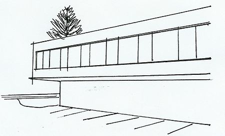
In architecture
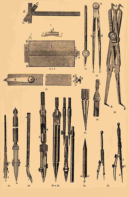
Drawing tools
Some modern tools:
When the drawing is large or subject to coloring, the paper for it needs to be pulled on drawing board . A good drawing board should represent a completely flat smooth surface and be soft enough to be easily punctured with buttons for pinching paper. Therefore, drawing boards are made of linden, pine or alder wood, and harder varieties are not suitable. The tree, as is known, can be shrouded from drying out, therefore for reception of a good drawing board it is necessary to take various measures. The tree is chosen to be straight-lined, if possible without knots: over surface cracks on the edge, it is easy to see that the fibers in the tree are curved almost always along a helical line, usually very steep. If the board from such a tree is aligned perfectly flat, it will become a "slanting plane", that is, parabolic hyperboloid , when it dries. If it dampens, it will twist in the opposite direction and form a surface of the same kind, but incapable of coinciding with the first. A straight-layered tree is bent into a cylindrical surface. On the basis of this, choosing boards, they are sawed along in half and glued in shields, turning each 180 ° relative to the neighboring ones: as a result, instead of one cylindrical surface, during warping, we get a wavy, less distant from the plane. The boards take one and a half inches and from the backside they clog "dowels" in the "reward". The edges are as straight as possible, as they are used for parallel lines, and knots on the front are hollowed out and sealed with pieces of wood from the same board. After a few months of staying in the heated room, the new board is highly jarring, then it is sent to the joiner for correction: while the thickness is sufficient, it can be flattened again flat, but this becomes impossible if it has been "driven" a lot. After the first inevitable correction, the board will not change much, but still requires at times overloading. Sometimes it is required that the board is light: then it is made empty, attaching thin shields on both sides of the frame. Such work is possible only with the use of a very dry and long-lasting tree. In the old days, boards were made in the form of a frame that was flush with the flush, but such boards, when dried, inevitably give crevices along the sides, and dampened, spilling the thorns of their frame. Also gluing boards from several layers of crisscrossing thin veneers, but for all their strength and lightness, they become incorrectly wavy when their initial degree of dryness changes. If you need to use both surfaces of the board, then it is made with "end gains" made of solid wood, that is " fold "Choose in the awards themselves, and the edge edges of the shield are dressed appropriately and slaughtered in this fold. For drawing, the board is placed on the table so that the light falls from the left hand of the worker and from the front, otherwise it will be necessary to draw lines along the shadow side of the rulers and angles. When covering with paints, the board has to be tilted slightly so that the liquid paint itself flows in one direction, when the drawing is very large, the board is conveniently very tilted and standing, otherwise you will have to lie down on the table to reach the more distant edge. Many more or less complex machines for this purpose have been invented; American is quite convenient. In it the board D rests on the goats, one aca frame is one-piece, while the other consists of the immutable part d and the interchangeable bb; chains fmf allow you to make even smaller changes in the slope. For the convenience of work on a heavily inclined drawing board, a specially adapted horizontal ruler ("winchel") is required, slid parallel to itself along the guides arranged on the sides of the board, and equipped with a ridge like a school black board: without this you can not release any tools, for it will roll down to the floor. To glue the paper on the board, its underside is wetted evenly with water using a clean sponge and put this side on the board (the underside of the paper can be distinguished from the face by viewing it against the light, with sliding lighting on the underside, the prints of the wire cloth on which the paper mass was scooped out to form sheets ). Then, on the width of the finger from the edge, put a stiff ruler on it, bend the edge of the paper upwards and, pressing the ruler with one hand, another brush the bottom surface of the paper and the board with a paste or a thick solution of gum arabic. After rubbing the smeared edge with a rag through a wrapped sheet of wrapping paper, repeat the same with the three remaining edges of the sheet, trying to stretch the middle without folds. After that, wet and the front side with a sponge, do not soak the glued edges this time, and leave to dry.
| List of drawing tools and their use | ||
|---|---|---|
|
Drawing tools. Fig. 1 |
Drawing tools. Fig. 2 |

Drawing lines, angles and vortices are used for conducting straight lines; the success of the work depends on the correctness, correctness and expedient arrangement of these devices. The best material is a straight-layer pear tree, but few masters know how to choose and process it so that it does not subsequently change its shape. The best rulers are obtained from Paris, with the hallmarks of H. Oliverau, Hudelo and E. S. with the image of a compass, triangle and protractor; German products are not inferior to this in the thoroughness of the finish, but soon warped when working. The thickness should be about 2 mm; directs the actual upper edge, since the line is always drawn slightly away from the ruler; so with a very thick ruler, the line easily emerges wavy due to small changes in the inclination of the pencil, and with very fine mascara it can easily stick to the tree and produce a blob. Squares make cut out of the board, but very large in the form of a frame. Due to the desiccation of the tree, the hypotenuse of the triangles cut from the solid board can not retain its original straightness, and therefore it is safer to use one of the legs when possible. Angles of 45, 60 and 30 ° are used, but usually sharp angles are made at random. Copper inserts do not do any good, because they are not strong. The correctness of the ruler can be judged by eye, viziruya against light along its edge; you can even more accurately test three rulers: they should not miss the light when they are superimposed by ribs in pairs, one on top of another. The coincidence of the same edges only two rulers can occur if they represent a convex and concave arc of the same circle. Small inaccuracies of the rulers can be corrected by rubbing the edge on a sheet of small glass paper laid on a flat board, and rough potholes are scraped off with a good jointer, very sharply carved, most conveniently on " stools ". For conducting parallel lines it is necessary to make the square slide along the fixed ruler, it is more convenient for this " voyage ": Its transverse part is thicker than the longitudinal one and slides along the edge of the drawing board. It is common to carry a lot of horizontal and vertical lines; if the edges of the board are neat at a right angle, you can use them with the fixed transverse part of the voyage; for inclined, half of this part can be turned and fixed with a screw. In Fig. 8 of the table is a board F with a flute AA ", in which the transverse part B slides along the fold in the edge of the EE board, while the spring cc of the clamp d rests on the right edge." Such a device is particularly convenient for C. on a strongly inclined board, for vertical lines (shown in dotted lines in Figure 8.) From this figure it is clear that the crosspiece B must be flush with the surface of the board, and the ruler AA "above, otherwise it will be impossible to bring the square close to the left edge in a convenient drawing position. There are many designs that allow you to change the angle of the winch to the desired number of degrees, correct its position with a micrometer screw, etc. Almost all of this turned out to be inconvenient or fragile. When drawing gears, etc., the figures have to draw a lot of straight lines converging at one point: you can simply stick in this place a pin of the same thickness as the pencil point and apply one end of the ruler to it; more convenient "eccentric ruler" AA. At one end, the copper lever B, equipped with a needle O, rotates and is secured with a screw N, which can be turned off as much as necessary and make the edge of the ruler go through the center or pass a certain distance from it.
Curvilinear rulers are called curves; they are usually cut from a pear tree and give very fantastic shapes, and, however, in a single pattern, usually pieces of homogeneous geometric curves are joined together. Produce and systematic selection for custom curves, for example for a parabola. The curves are used for C. curves along points. When the curvature is smooth, you can bend the elastic steel strip so that it passes through the given points and traces along its edge; for success, the strip must be held by the assistant or pressed with special weights. For arcs of a circle of very large radius, there are special mechanisms of Chebyshev and Prince Gagarin, bending an elastic strip along a given radius. An experienced draftsman very soon makes hatching by parallel lines, moving the square along the voyage by hand, without the need for special devices that exist in large numbers. The simplest is shown in Fig. 13 of the table: the square B can slide along the cutout ab of the ruler A. Moving it to a, draw a line, pushing towards b, hold the second; Then, holding B, move A to the right, and repeat the same. Many inventors have tried with greater or less success to make distances between strokes of variables. In addition to wood, the squares are made of horny rubber and celluloid. Rubber is less volatile than wood, it warps only from a fairly strong heat, but it is black, dirt and stains from the carcass are not visible on it, and therefore it easily dirts the paper. Celluloid, it may be, will be convenient, since in recent years he was able to give more strength and less inflammability. Metal rulers are too heavy, and copper to that they themselves darn paper; Steel is used only for cutting finished drawings.
The main tool of the draftsman is a drawing pen or " drawing pen ". It consists of two springs aa, a screw c and a handle b, between the leaves liquid mascara is held by capillarity; if both leaves fit well to the paper, then the ink sticks to it between them, the dash comes out sharply limited. The newest type, manufactured by Kern and Gisi in Switzerland, and also Gerlach in Warsaw, is shorter and stronger to eliminate the narrowing of the gap from pressure on the ruler; it is cut from one piece, supplied with a longitudinal slot and screw a for reinforcement in the handle. For thin lines, the ends are rounded sharper, and for thick ones, duller, so that more ink is kept between wide flaps. In the old days they made one leaf on the hinge to make it easier to clean, but the hinge very soon loosened up, and it was not difficult to clean the hinge, soaking the penis in the water. Lines thicker than 1 mm are difficult to carry out at once, usually only many thin lines are drawn. Therefore, for a good pen-finder, the following qualities are needed: both its flaps should touch simultaneously to the paper; When the line is drawn at a convenient distance from the ruler, the edges of the leaflets should be smooth and thin, but do not cut the paper. To the width of the slit, the width of the touching edges of the leaflets is added, so that for a thin line they must be thin, but not sharp. The gap between the leaflets is wedge-shaped, and on the side they are rounded, which means that the line will be thinner when the drawer is held vertically, and the wider it is. But the device of the human arm tends to change itself, when they lead a long line, and the devil knows a lot of skill in order to avoid this defect. Therefore, the very tips should be slightly bent from the inside, so that, with the usual width of the dash, their inner surfaces are close to parallel. Unconscious observance of this condition also makes the fact that another penning worker works better than others. From the use of pen-drawing will soon be blunt, but the draftsman can easily correct them himself; for lithographers the ends of the leaves are tempered, in that case they should be grinded on the bar, and ordinary, soft, you can return the old form with a small file. First, slide the flaps to a mutual touch, the tips are grinded from the sides, not paying attention to the fact that the edges become thicker. Having done this, the drawing pen is opened to the usual width and make sure that both doors are touching when the line is drawn at a convenient distance from the ruler. After this, you can restore the parallelism of the inner surfaces of the leaflets at the very end to maximize their approach and carefully smooth them with sandpaper. If the edges on the inside are too rounded, they should be sharpened again on the sides. Then you need to carefully trim the doors from the outside until their edges become almost sharp. So that they do not cut the paper, you need to take a piece of the smallest sandpaper, put it on a fairly soft lining, for example, on thick paper, and carry it through an opened pen drawer twice or twice, deliberately changing its inclination on either side of the vertical line. The unevenness of the edges will be smoothed out, and the drawing pen will scratch it cleanly and gently. If he still cuts the paper, you need to repeat the procedure, but carefully, and then the inner edges are too rounded and the delicate features can not be held. For fast installation on the set thickness of the line, a "calibrated" drawing pen is convenient; for thick lines - double drawers: you can run the mascara to the ends 1 and 3 of the pen drawers a and b and, at once double line, fill the gap between them with a brush, or, bringing the ends of the robot close together with Rob, insert mascara into the gap 2. For this very wide lines the carcass is not enough, and it's easy to make a blot. To facilitate the drawing by the templates, the pen-finder is made curved; when the nut A is released, it turns around the handle axis, in B. There are many devices for the dotted lines, but they are all not good or work too slowly.
The design documentation defines the device and the composition of the product, contains the necessary data for its manufacture, control, acceptance, operation and repair.
Depending on the information presented in them, the design documents are divided into graphical (drawings and diagrams) and text documents (specifications, explanatory notes, calculations, statements, instructions, technical conditions, etc.).
In the graphic design document, the basic information about the technical subject is presented in the form of a graphic image executed in black with the help of lines, strokes and dots. Information On the subject in the form of a graphic image is most convenient when considering the device and the principle of the product, the relative location and arrangement of its constituent parts, the geometric shape of the parts. Often, graphic information is accompanied by text or character (signs and numbers) information. Text documents contain verbal descriptive information, as well as calculations and their results. Text document is made in the form of solid text or text, broken into columns (specifications, sheets, tables, etc.).
ESKD standards (GOST 2.102-68) provide for the nomenclature
design documents. The most common documents are a general drawing, a drawing of a part, a specification, assembly drawing, diagram, explanatory note, calculations.
The general drawing contains images assembly unit and other data necessary for understanding the principle of operation and interaction of the constituent parts of the assembly unit. A general drawing is the basis for the development of parts drawings and specifications.
In Fig. 1.1 is a drawing of a general view of an automotive three-phase synchronous alternator with electromagnetic excitation. The figure shows a generator image consisting of a longitudinal section, a left view, and a view of silicon diodes (type B) mounted in a rectifier block. The drawing also contains textual information in the form of the names of the components of the generator, data on the excitation winding, stator winding, technical characteristics. The images bear overall and connecting dimensions.
The drawing of the generator gives an idea of its design. The core of the stator, which is a magnetic core, is fixed between the two covers (left and right) using four clamping screws. To reduce eddy currents, the core is recruited from thin sheet plates. The internal surface of the stator has 18 teeth, which are worn
Fig. 1.2. Design document - drawing of the detail "Nut"
Fig. 1.3. (see scan) Design document - drawing of the detail "Cable"
18 stator coils (see data "Stator winding").
The rotor consists of two six-pole tips. The tips of one half of the rotor enter the grooves between the tips of the second half. In the cavity between the tips of the rotor is placed an excitation coil fixed to the magnetic core, made in the form of a sleeve, set on a splined shaft. The bearings of the rotor are two ball bearings, which are filled with grease and protected by O-rings.
The leads of the field winding are connected to the contact rings, to which two generator brushes are pressed by the springs. One of the brushes is connected to a plug-in terminal, the second one is connected to the generator housing.
The drive of the generator is carried out from the engine of the car by means of a belt transmission, the shaft of which is fixed to the shaft of the generator with the help of a segment key. The same key transfers the rotation of the impeller, which serves to cool the generator.
In the general drawing, how
rule, do not provide the information necessary for the manufacture of parts and the implementation of assembly. These data are placed on the parts drawings and assembly drawings. The main purpose of the general drawing is to give an idea of the device of the assembly unit and the interaction of its constituent parts.
A part drawing is a design document containing an image of a part and other data (dimensions, dimensional deviations, surface roughness, material information, etc.) necessary for its manufacture and control.
In the drawing of the "Nut" part (Fig. 1.2) the image of the part is shown, all dimensions and their limiting deviations are plotted. The roughness of the surface is denoted:. In the corresponding column of the main inscription, the name and
Fig. 1.4. (see scan) Design Document - Specification
grade of the material: "Alloy LS-59-1" according to GOST 15527-70.
The graphic and text information placed on the drawing completely defines the geometrical shape of the part and allows to make it with the required degree of accuracy from the material of the given mark.
The workpiece for the part shown in Fig. 1.3, is a piece of cable of grade RK 50-2-22 according to GOST 11526,74-79. The manufacture of the part consists in the fact that it is necessary to remove a part of the insulation and braids for a given length. Then the bare ends of the cable core should be soldered. Therefore, the dimensions indicated by * are given without limiting deviations. Roughness of the surface is not indicated, but the data on the solder are given.
The composition of the assembly unit, the necessary information on connecting the parts to the assembly unit, and the requirements for the finished assembly unit are given in the specification and on the assembly drawing. The specification and the assembly drawing are independent design documents, but are developed jointly.
The specification is a text document that contains information about the composition of the assembly unit. The specification (Figure 1.4) is a list of documents related to this assembly unit and the components of this assembly unit. The list is drawn up according to a certain form and in a certain sequence determined by GOST 2.108-68.
Fig. 1.5. (see scan) Design document - assembly drawing
(click to view the scan)
Fig. 1.7. (see scan) Design document-explanatory note
The assembly drawing contains a simplified image of the assembly unit and other data necessary for its manufacture (assembly). In the assembly drawing (Fig. 1.5), the component parts of the assembly unit are supplied with the leader-blocks, on which the positions of these components are placed in accordance with the ordinal number of the position in the specification. The assembly drawing (Figure 1.5) contains the requirements for soldering conditions of item 2 and the overall size for the length of the HF cable after assembly.
The diagram is a design document, in which the component parts of the product are shown in the form of conditional graphic symbols, as well as the connections between them. Depending on the elements included in the product and the connections between them, the schemes are divided into the following types (GOST 2.701-84): electrical, hydraulic, pneumatic, gas (except pneumatic), kinematic, vacuum, optical, power, fission, combined.
The purpose of the circuit determines its
Fig. 1.8. (see scan) Sample text of explanatory note
type: structural, functional, principal (complete), connections (mounting), connection, general, location, combined.
Scheme kinematic principle "Electric drive" (Figure 1.6) contains:
a) an image of the circuit, which consists of the conditional graphic symbols of the elements, the links between the elements, the alphanumeric positional designations of the elements;
b) the list of constituent elements of the scheme, executed in the form of a table.
In the image it is possible to imagine the transmission and transformation of motion in the electric drive from the engine to the driven link. The list of composite elements explains the designations of the elements and gives some of their parameters.
Explanatory note (GOST 2.106-68) contains, in general, information about the purpose and scope of the product being designed, the technical characteristics, the description of the device and the principle of the product's operation, the justification of technical decisions taken in the development of technical and economic indicators.
The first sheet of the explanatory note is the title page (Figure 1.7), which is executed in A4 format and contains
the name of the ministry or agency that developed the document, the product code for the All-Union Product Classification (VCL), the approval and approval stamps, the product name, the document designation, the document's signatures, the year of publication of the document. An example of an intermediate page of the explanatory note is shown in Fig. 1.8.
(see the scan)
Calculations include a sketch or a scheme of the calculated product, a calculation task, data for calculation, calculation conditions, calculation, conclusion.
From other design documents should be mentioned:
a) theoretical drawing, which determines the geometric shape (contours) of the product and the coordinates of the location of the components;
b) dimensional drawing, containing a contour image of the product with overall, mounting and connecting dimensions;
c) an installation drawing required for the installation of the product at the site of use.
Each design document has a code in accordance with GOST 2.102-68. So, the general drawing has an assembly drawing code - an explanatory note - PP, etc. The scheme code according to GOST 2.701-84 consists of the code of the type and type of the scheme. Drawing details and specification of the code do not have. This is due to the fact that these documents are accepted as the basic for the detail and the assembly unit. The ciphers of the remaining design documents are given below (see § 1.5).
Any object or set of items of production to be manufactured in the enterprise has a common name - product.Products distinguish basic and auxiliary production.
The products of the main production include items of production included in the product range of the enterprise and intended for delivery (sales).
The products of auxiliary production include products that enterprises manufacture only for their own needs.
For manufacturing of products of the main production, the enterprise can purchase products of other enterprises. In this case, the purchased product is called purchased (except for items obtained in the order of cooperation).
Products are divided into the following types: parts, assembly units, complexes and kits.
Depending on the presence or absence of components in the products, they are divided into unspecified (parts), i.e. not having component parts, and on the specified (assembly units, complexes, sets), consisting of two or more component parts.
Detailis a product made of a material that is homogeneous by name and brand, without the use of assembly operations.
Assembly Unit -this product, the component parts of which are connected together in the enterprise by assembly operations.
Complex- these are two or more products not connected to each other at the enterprise by assembly operations, but intended to perform interrelated operational functions.
Set- these are two or more products not connected at the enterprise by assembly operations, but representing a set of products having a general operational purpose of an auxiliary character, for example: a set of spare parts.
The composition and design of the product are determined design documents.Types and completeness of design documents are established in accordance with GOST 2.102-68. At the same time, design documents include graphic and text documents that individually or collectively determine the composition and design of the product and contain the necessary data for its development or manufacture, control, acceptance, operation and repair.
Drawing detailscontains an image of the part and the necessary data for its manufacture and control.
Workpiece Sketch - a graphic document of a temporary nature, made without the use of a drawing tool on any material without accurate scale compliance. It is designed for one-time use and contains an image of the part and the necessary data for its manufacture.
Assembly drawing(document cipher - SB) contains the image of the assembly unit and other data necessary for its assembly (manufacturing).
General drawing(VO) determines the design of the product, the interaction of its main components and explains the principle of the product.
Theoretical drawing(PM) determines the geometric shape (contours) of the product. It gives the coordinates of the location of its components.
Outline drawing(GCH) contains a simplified image of the product with overall, mounting and connecting dimensions.
Installation drawing(MCH) contains a simplified image of the product and the necessary data for its installation (installation).
The schemeIs a design document, in which in the form of symbols are shown the component parts of the product and the connection between them.
TO textualdocuments include the following:
Specification -the document that determines the composition of the assembly unit, complex or kit.
Explanatory note(PP) - document, which describes the device and the principle of the product, given the justification of the technical and technical-economic solution adopted during its development.
Technical specifications(TU) - a document containing the requirements for the product, its manufacture, control, acceptance and delivery.
In addition, the design documents include various statements, tables, calculations, operational and repair documents.
Depending on the method of execution and the nature of use, the design documents and, in particular, the drawings are divided into the following types.
Original- a drawing that serves for the originals.
Script- Drawing, issued by authentic signatures of officials and allowing multiple copies of copies (it is allowed to use the original as the original).
Duplicate- a drawing that repeats the original; is intended for making copies.
Copy- a drawing identical to the original or duplicate; is intended for direct use in production.
Any of the listed documents (drawings), intended for one-time use in production, can be executed in the form of a draft design document (drawing).
Depending on the stage of product development, the documents are subdivided into design and working documents (working documentation).
TO project documents include: terms of reference, technical proposal, draft design and technical design - a set of design documents that give a complete picture of the device and the design features of the designed product. Drawings of general types included in the technical design should contain the initial data for the implementation of working documentation on them, for example, working drawings of parts.
Workingdocumentation is the final stage of design and contains the documents necessary for the manufacture, assembly and control of products and their components in the production and repair process during operation. The working documentation contains a set of parts drawings, as well as assembly and installation drawings of the product and its specification.
Each product is assigned an independent designation, which can no longer be used for another product. In accordance with the designation of the product, all design documents for this product are also indicated.
Control questions
What is the standard?
The main purpose of standardization.
What is ESKD? What is its purpose?
What is a product? Types of products.
Name the types of design documents and their ciphers.
What is included in the text documents?
What kinds of design documents (drawings) are divided?
How are the documents divided depending on the stage of product development?