Goals and objectives:
- systematize students' knowledge of graphic images;
- to educate attention and accuracy when performing graphic works;
- develop spatial thinking and imagination.
Equipment and visibility:
- tables
- tools for working on the board
- multimedia presentation equipment ( Appendix №1)
During the classes:
- Organizing time.
- Message of the topic of the lesson, goals (slide # 1).
- Exploring a new topic:
Teacher
: Today we begin to study a new subject. In the school course of drafting, you will study the theoretical basis for constructing various graphic images, the rules for their design, master the techniques of drawing and measuring instruments, learn how to perform images by hand, and get acquainted with various conventional images and notations. All this will help to learn to understand, or, as they say, read, blueprints. (slide number 2) Reading and drawing drawings contribute to the development of spatial representations that are of great importance in the practical activities of a person, accustom them to accuracy and accuracy in their work. The drafting course introduces some issues of industrial and technical nature, the use of drawings in various branches of the economy, and teaches us how to use manuals on our own.
At school you have already read many graphic images. For example, in the classroom visual arts you performed from nature drawings of objects. In math lessons, you met with diagrams and graphs. Plans and geographic maps you used in the lessons of natural history, geography, history. The lessons of physics, as well as in the classes on technical and servicing work, were applied by schemes. They use the symbol to convey the principle of the work of products. A drawing, a diagram, a map, a diagram are all examples of graphic images (slide # 3).
The main design document, which produces, controls, installs and repairs the product, is a drawing - a graphic representation of the product or part thereof. Each product must be pre-engineered by the designer. In the process of designing products, drawings, sketches, diagrams, and drawings (slide No. 4) are performed.
"Historian":
The design and content of the drawings changed with the development of society. Images of various subjects - drawings - appeared as a means of communicating people even before writing. Later, during the construction of dwellings, fortresses and other structures, the first drafts appeared, which were called "plans". These drawings were usually carried out in full size directly on the earth's surface, at the site of the future construction (slide No. 5). For the construction of such drawings, the first drawing instruments were created-a wooden compass measuring instrument and a rope rectangular triangle. Later such plans-drawings began to be performed on parchment, wood and canvas in a reduced form. In the drawings, they tried to show both the shape and dimensions of objects (slide No. 6). In ancient Russia there were a lot of skilled masters in casting metals and their alloys, making weapons, building buildings. These masters, as can be seen from the remaining buildings and structures, very well imagined the geometric shapes of objects and knew how to choose the best solution of technical problems. So, for example, in the annals of the 13th-14th centuries. found graphically executed drawings, which you can learn how to make objects. Considering it can be determined that the barrel of the cannon is made by forge or forge welding and is strengthened with band-rings. Often, in one image, a plan (top view) and a facade (front view) of a structure, for example a bridge, were combined. The inconvenience of such a combination made it necessary to separate both species and apply two, three or more species when imaging objects. In the second half of the 16th and early 17th century. in Russia at the metalworking plants, the products were manufactured not according to the drawings, but according to the model models. At the end of the seventeenth century, drawings began to be used instead of samples. These drawings were carried out without exact scale compliance, but the sizes of products on them were already applied.
When the shipbuilding began to develop rapidly, more precise drawings drawn on a strict scale were required. Ship drawings of 1686-1751, made by masters and their assistants, are already more perfect. Here, three images were used, with the help of which it was possible to show the dimensions of the vessel's three dimensions on the plane of the drawing: length, width and height. In 1798 the French engineer Gaspar Monge published his work "Descriptive Geometry", which formed the basis for projective drawing. Paying tribute to Gaspar Monge, who generalized the method of rectangular projection of objects into two mutually perpendicular planes of projections, we must not forget that long before the appearance of descriptive geometry in separate Russian drawings, the same tasks that Monge had scientifically generalized were solved and solved. In the XVIII century. drawings were carried out extremely carefully, with a stroke of colored mascara. These drawings made conditional sections of products with the coloring of the cut location in different colors, depending on the type of materials of the products. Drawings by II Polzunov and I. P. Kulibin clearly demonstrate the excellent knowledge of Russian inventors in the field of constructing an accurate projected drawing of a product. The founder of descriptive geometry in Russia was prof. Ya. A. Sevastyanov, who in 1821 published his course "Foundations of Descriptive Geometry." An outstanding scientist of the late nineteenth century. prof. VI Kurdyumov wrote a series of capital works on descriptive geometry. Prof. NA Rynin has a number of works on the application of descriptive geometry in engineering and a textbook, which is also used today. Prof. DI I. Kartin wrote a paper "On the Accuracy of Graphic Constructions." Of great importance are the works of a major scientist prof. AI Dobryakova on descriptive geometry. Prominent scientist of our time prof. NF Chetverukhin wrote a large number of works in the field of the theory of images.
At present, scientists conduct theoretical research in the field of descriptive geometry and engineering graphics, are working on the creation of instruments and apparatus for mechanization and automation of drawing and design work and reproduction design documentation, develop new standards.
A group of students dressed in costumes (slide No. 7) is leaving.
We will tell you about what is necessary to work in drawing lessons (the most complete historical information about materials and tools in Appendix №2).
"Textbook": I'm a textbook. Each of you was given in the library the same. Carry it for lessons. In it you will find many interesting and useful (slide # 8). See how I have changed with time. Today my friends came to me with you, meet them and make friends (slide # 9).
"Pencil" : Drawing works are performed in most cases with pencils (slide No. 10). When drawing a drawing with thin lines, it is recommended to use a pencil of the T-mark. Draw lines of the drawing with a pencil of M mark; When drawing with softer pencils, the drawing becomes dirty. Thus, the student must have a minimum of three pencils: M, TM and T. Picking up a pencil of the required hardness, it is sharpened.
"Paper": Drawings, as a rule, are performed on dense drawing paper. The paper is chosen such that the pencil lines with it erase well with eraser (slide No. 11).
"Preparing": The preparation is a set of drawing tools laid in a case (slide No. 12). And what tool you will need very often in drawing lessons, you will learn by solving a riddle:
He circled on one leg,
Another one writes in an arc,
Turning then in the profile, the full face,
Everything is rounded off for you.
Having done a full turn,
He will finish where he starts:
To the starting point is suitable
And his line will be closed.
"Compass": That's right, this compass is the oldest among your brothers instruments (slide # 13).
Teacher:
In addition to these materials and tools in drawing lessons, you will need a ruler and triangles (slide # 14).
Today, in practical work, you will learn how to draw vertical, horizontal, inclined lines and circles with a ruler, squares and compass (slide No. 15).
Before you begin to do practical work, you should learn the following, from the correct preparation of a working place depends largely on the quality of the drawing. The light on the drawing must fall to the left from above. In this case, shadows from tools and hands will not interfere with the work. While doing the drawing, you should sit straight, not hunching. The distance from the eyes to the drawing should be approximately 300mm. On the table leave only those tools that are needed to work at a given time. At the same time, the set of pieces, angles, pencils and gum should lie on the right, and the book on the left. Do not bend over the drawing.
4. Practical work: "Performing vertical, horizontal, inclined lines and circles."
Teacher: Using drawing tools, draw vertical, horizontal, inclined lines and circles in the workbook. Try to conduct all the lines of the same thickness, beautifully arrange the groups of lines on the notebook sheet (slide No. 16).
5. Summing up the lesson.
6. Homework (slide number 17) (

Image of the mill on the river Seven (17th century) Drawing of the bridge and watchtower (17th c.) The drawings in Russia were made by "draftsmen", a mention of which can be found in the "Pushkarskiy order" of Ivan IV. Other images - drawings-drawings, represented a view of the construction "from a bird's eye view"

The history of the appearance of graphic methods of images and drawings At the end of the 12th century, In Russia large-scale images are introduced and dimensions are displayed. In the 18th century, Russian draftsmen and Tsar Peter I himself executed drawings using the method of rectangular projections (the founder of the method is the French mathematician and engineer Gaspard Monge). By the order of Peter I the teaching of drafting was introduced in all technical schools.

Development of drafting in Russia The talented Russian mechanic, designer and inventor IP Kulibin (only to perform one of his masterpieces - a clock in the form of a chicken egg - produced several dozen drawings. Drawings of the locomotive of the father and son of the Cherepanovs (XIX century) illustrate not only the high level of engineering graphics development in Russia at that time, but also a high level of technical thought.

The entire history of the development of the drawing is inextricably linked with technical progress. At present, the drawing became the main document of business communication in science, technology, production, design, construction. It is impossible to create and check the machine drawing without knowing the basics of the graphical language. With whom you will get acquainted, by studying the subject "Drawing"


Materials, accessories, drawing tools. In the beginning of the XXth the work on mechanization of the designer's workplace was started. As a result, drawing machines, drawing and writing instruments of various systems appeared, which made it possible to speed up the process of drawing.


Riddle about drawing tool He circles on one leg, Another one writes in an arc, Turning it in profile, it's full face, Everything rounds it for you. After completing a complete turn, He will finish the same place where he starts: At the starting point he will approach And his line will close. Iron compasses were found on the territory of France in the Gallic barrow of the 1st century AD. In the ashes that fell asleep to Pompey nineteen centuries ago, archaeologists also discovered a multitude of bronze circuses. In ancient Russia was circulated a circular ornament of small regular circles. A steel circular cutter was found during excavations in Veliky Novgorod.

Riddle about the drawing tool "For me, an elastic band, brothers, Fierce enemy! I can not talk to her. I made a cat and a cat - Beauty! And she walked a little - No cat! You can not create a good picture with it! "- This is how I used to scold the rubber band ... (pencil) The pencil got its name from the confluence of two Turkic words: kara-black and tash-stone. In the 16th century, the British found a deposit of graphite. Fragile little pins were placed in a graceful rim of reed or mahogany and only in the late 18th century, the Czech J. Garmouth proposed making writing sticks from a mixture of crushed graphite and clay. The pegs for the letter were called "kokhinor" - "not having equal".

Triangles and rulers All segments are friends to me - Small and long ... Who recognized? Ruler is me. The tool is vintage. I do not remember all of them, There were so many ancestors. In Ancient Rome - a line, In Russia - the rule ... To introduce you to relatives I will not fail here: The triangle is my brother, A sister is a voyage. To many who have recognized me, I will be of use to you everywhere, Apply many scales - I will scale.

Transporter - a tool for degree measurement and plotting angles, made of tin or plastic. Lekala Lecala is a thin plate with curvilinear edges that serves to draw curves (local) lines that can not be drawn with a compass. Protractor and patterns

Plan - abstract lesson Drawing
Subject: Introduction . Educational subject "Drawing". Instruments. Standards. Formats
date : ___________________
Class: _________________________
Objectives: explain the goals and objectives of studying the subject of "drawing"; consider the history of the emergence of a graphic language and a drawing in a modern form. To trace intersubject connections of drawing, connection with life; actualization of the study of the subject, the need to read and understand the drawings; explain the correct use of drawing tools by performing training exercises in a notebook; develop skills in working with drawing tools; to acquaint with drawing design, formats, GOSTs, to teach to carry out the basic inscription.
Equipment: a visual aid depicting Egyptian hieroglyphs and examples of using drawings in life (apartment plan, house design, detail drawing, etc.); examples of drawings: drawing of a part with dimensions, assembly drawing, part sketch, electrical diagram, part scan, axonometric drawing. Drawing accessories for demonstration wooden rulers, angles with angles of 30 and 60.90 and 90 °, compasses, properly sharpened pencil, vortex. The issued sheet of a format A4 with a frame and the basic inscription. Table with drawing lines and their characteristics.
During the classes
Organizing time
A greeting, a test of readiness for the lesson.
Acquaintance with new material
Introductory conversation.
Guys, today we are starting to study a new subject "drawing", which refers to technical disciplines.
There are various means by which people transmit to each other a variety of information.
What examples can you give? (Writing, speech, drawings, signs, sounds, gestures, etc.)
In ancient times, people had a need to transfer information to each other, which led to the emergence of various languages, including graphic language.
What can be calledgraphical language ? (This is written language, and images, and lines, numbers, signs.)
Graphic language arose and developed in the extreme antiquity, when the visual letter was the only way to preserve information. Graphic language has gone a long way.
What example of the most ancient graphic language that has come down to us you can bring?(Egyptian hieroglyphs.)
The ancient Egyptians conveyed their thoughts with the help of signs-drawings, which were called hieroglyphics. Scientists have traced a long way, going from pictures to modern letters.
To indicate the places of hunting, the ways of nomadic movements, plans for the past, which in the course of time became more detailed, more expressive, more accurately, conveyed the character of the terrain.
What in modern life we can compare with such drawings?(Maps, terrain plans.)
Over time, the ways of the image changed and improved. In the Renaissance, the great Leonardo da Vinci performed graphic images of flying machines, propelling machines. The method used to display them is calledlinear perspective and is used today in architecture, painting, drawing.
Over time, perspective drawings were transformed into a special kind of graphic image -technical drawings andblueprints. The word "drawing" is originally Russian.
The appearance of the drawings was mainly due to the construction activities of a person. First they were carried out on the ground - on the place where it was necessary to build, and then began to perform on stone, clay slabs and paper.
How do you understand what a drawing is?(An approximate answer. The image of the object - details, machines, structures - from several sides in such a way that it is possible to build a house on this image, that is, indicating the dimensions, materials, etc.)
In the XIX century, mass production of products led to the development of precise rules for the implementation of drawings. The whole history of the drawing is inextricably linked with technical progress. At present, the drawing became the main document of business communication in science, technology, production, design, construction.
For many years the drawings were done manually using a compass, ruler, or gon. At the present time, computer-aided design methods have been created, which greatly simplified and accelerated this time-consuming process. However, it is impossible to create and read the machine drawing without knowing the basics of the graphical language, with which you will get acquainted, while studying drawing.
- The drawings can be different. Look at this drawing. (The teacher shows any drawing of a simple part in the textbook.) Before us is a simple part drawing. What does it contain besides the detail image? (Dimensional numbers, text, information about the material.)
Such a drawing gives a complete idea of the details.
To assemble a product from finished parts, specialassembly drawings. In the assembly drawing, the parts are shown in the connection and each part is numbered. In a separate table indicate the names of all parts. Look at the picture. (An assembly drawing is shown in the manual or textbook.)
Drawings executed by hand and by eye with observance of proportions, are calledsketches. (A sketch is shown in the manual or textbook.)
Images are also applied that simplify and conditionally convey the principle of the product. Such images are calledschemes. Schemes are kinematic, radio, electrical, etc.
In the next image you seesweep a part made of sheet material.
Drawing also uses visual images of objects -axonometric drawings andtechnical drawings. (An example of a manual or textbook is shown.)
Tools and materials.
The quality of the drawing depends on the tools, materials and other accessories that you will use when performing it.
Drawings are made with pencils of a certain hardness. A soft domestic pencil is indicated by the letter M
on the lateral side, solid - letter. T, medium softness pencil - TM. On foreign pencils the notation is as follows: H - solid, B - soft, HB - hard-soft. The degree of hardness is indicated by the figure facing the letter, for example 2T, 3M. The larger the number, the harder or softer the rod.
To draw a drawing, use pencils T or 2T, sharply sharpened, and for a stroke - T or TM, sharpened with a "spatula" for thicker lines.
To carry out drawings use special paper - a white dense drawing, as well as a tracing paper - to copy the drawings.
Eraser for convenience is cut diagonally, this allows the sharp corner to gently erase unnecessary lines.
To draw arcs and circles use a compass. The graphite core of the compass should protrude 5-7 mm, approximately the same as the needle.
Rulers are more convenient to use wooden ones, since they do not stain the drawing. The optimal length of the ruler is 30 cm.
A trolley is a ruler with a cross bar (stop) at one end. It is used to draw parallel lines.
Horizontal lines are drawn from left to right along the edge of the ruler. (Demonstration on the board.) Vertical - from top to bottom. To obtain a clear line, the pencil is set perpendicular to the plane of the sheet and then tilted toward the direction of motion. To make the line the same thickness, the pressure of the pencil on the paper should be uniform. To obtain a clear line, the pencil can be re-drawn in the opposite direction.
Lines can be parallel and intersecting. To build parallel lines, use a flowner, a gon and a ruler or two angles.
For example, in order to draw a line parallel to the given line, at a distance of 5 mm, one must take any gon and attach it with a leg to the given line. To the second leg, attach the ruler with the markings in the side of the square, holding it with the left hand, move the right angle along the ruler by 5 mm and draw a new line. (Demonstration on the board.)
Draw in the notebooks of 5 parallel vertical and horizontal lines, as well as 5 inclined lines at an angle of 60 °. (If necessary, re-demonstration on the board.)
How to draw a line at an angle of 60 °?(On a corner with angles of 30 and 60 °.)
In the notebook in the cell, you can put 3 cells aside and 5 up or down, we also get the angles of 60 and 30 °.
Standards. Formats.
If each engineer performed and executed the drawings in his own way, not following the uniform rules, then such drawings would not be understandable to others. To avoid this, unified rules for the development and design of technical documentation. They are designed in a set of state standards (GOSTs) and are called the Unified System of Design Documentation (ESKD).
For the first time in our country standards for drawings were introduced in 1928. Over time, the GOST was amended, so GOST is also assigned its number indicating the year of its registration.
Drawings and other design documents are carried out on sheets of certain dimensions, calledformat. School drawings are carried out on A4 sheets, the dimensions of which are210 x 297 mm. The produced sheets usually have a slightly larger size, so it is necessary to measure the sides and cut off excess edges.
The basic formats are obtained by successive division parallel to the smaller side.
AO - 841 x C89 mm;
А1 - 841 х594 mm;
A2 420 x594 mm;
AZ - 420 x 297 mm;
A4 - 210 x 297 mm.
Each drawing is framed by a frame that limits its field. It is carried out from above, below and to the right at a distance of 5 mm from the edge of the sheet, and on the left - 20 mm (for filing). The border line is a solid thick main.
In the lower right corner placethe main inscription. Its shape, size and content determine the standard. A sample of the filled inscription you can see in the textbook. It is also performed by a solid thick main line.
Practical work
Construction of the main inscription.
The sequence of building the main label is as follows. I show on the board, and you repeat in the notebooks.
First, we construct the dimensional rectangle of the inscription: lay the length (145 mm), then the height (22 mm) and draw a horizontal and then a vertical line with the help of a square and a ruler.
On the length to the left we measure 70 mm; we draw a vertical line.
On the left side of the rectangle measure the top two times 7 mm; the same thing is done on the segment, which we carried along the length of 70 mm; we draw through these marks two horizontal lines, the first from above - the length is also 70 mm; the second from above is a length of 145 mm, to the end of the outer rectangle. Line from left to right.
We indicate the length of the first block on the left - 25 mm and the third (right) block - 15 mm. We draw vertical lines on the top two graphs. Thus, we get two upper blocks of three columns in each, and the bottom one remains integral.
Now in the right lower block we measure on the right two times on20 mm and conduct two vertical lines, dividing the lower block into three parts.
The main inscription is ready for us. Now you need to push it hard, draw it around the ruler with a softer pencil, but so that all lines are the same thickness. In the intersection of lines should not go one after another.
The main inscription is filled with a drawing font, which we will consider in the next lesson.
Summing up the lesson
So, today you have got acquainted with the new academic subject. What is called a drawing?
What is the standard? Why is it needed?
What is the format? On the sheets, what format will we work in school?
Homework Prepare and bring properly sharpened pencils of different hardness - TM and T (2T), eraser, ruler, squares, prepare A4 sheet of vertical format, measuring its dimensions (210 x 297) by drawing a frame on it (left on the long side should remain20 mm) and execute the main inscription at the bottom right. Do not fill out the text.
Subject: DRAWING Class: 9 Date _______________ Lesson # 1. Educational subject "Drawing". Instruments. Standards. Formats. Objectives: explain the goals and objectives of studying the subject of "drawing"; to consider the history of the emergence of a graphic language and a drawing in a modern form; tracing intersubject connections of drawing, connection with life; actualization of the study of the subject, the need to read and understand the drawings; explain the correct use of drawing tools by performing training exercises in a notebook; develop skills in working with drawing tools; to acquaint with drawing design, formats, GOSTs, to teach to carry out the basic inscription.Equipment: drawing accessories, visual aids, textbook.DURING THE CLASSES. 1. ORGANIZATIONAL MOMENT A greeting, a test of readiness for the lesson.2. INTRODUCING NEW MATERIAL . 1.Interior conversation. The subject of "drawing" refers to technical disciplines.There are various means by which people transmit information to each other.-What examples can you give? (writing, speech, drawings, signs, sounds, etc.)In ancient times, there was a need to transfer information to each other, which led to the emergence of various languages, including the graphic language. -What is graphical language? (this is written language, and images, and lines, numbers, signs). An example of an ancient extant graphic language, are Egyptian hieroglyphs.In the Renaissance, the great Leonardo da Vinci performed graphic images of flying machines, propelling machines. The method used to display them is calledlinear perspective and is used today in architecture, painting, drawing.Over time, perspective drawings were transformed into a special kind of graphic image -technical drawings and drawings. Word "drawing" originally Russian.The appearance of the drawings was mainly related to the construction activities of a person. First they were performed on the ground in the place where it was necessary to conduct construction work, and then began to perform on stone, clay slabs and paper.-How do you understand what a drawing is? (example answers-image of a part, machines, structures with dimensions and materials In the 19th century, mass production of products led to the development of precise rules for the implementation of drawings. The whole history of the drawings is connected with technical progress. At present, the drawing became the main document of business communication in science, technology, production, design, construction.For many years the drawings were done manually using drawing tools. At the present time, computer-aided design methods have been created, which greatly simplified and accelerated this time-consuming process. But to create and read machine drawings without knowing the basics of the graphical language. With what we will learn in drawing lessons. The drawings can be different. Look at the drawing (working with the tutorial.) Is this a simple part drawing that it contains? (dimensional numbers, information about the material)Such a drawing gives a complete idea of the details.2. Tools and materials. The quality of the drawing depends on the tools and materials, other accessories that you will use when performing it.Drawings are made with pencils of a certain hardness. Soft - M (B), hard - T (H), medium softness TM (HB).To draw a drawing, use pencils - T or 2T sharp-sharpened, for a stroke - TM or M, sharpened with a spatula (picture in the textbook).To carry out drawings use paper - a white, dense drawing, as well as a tracing paper for copying drawings.Eraser for convenience is cut diagonally, which allows the sharp corner to gently erase unnecessary lines.To draw arcs and circles use a compass. The graphite rod should protrude by 5-7 mm., Approximately the same as the needle.Rulers are convenient to use wooden, since they do not stain the drawing. The optimal length is -30cm. And also need a gon, protractor.Draw in the notebooks 3 parallel vertical and horizontal lines, as well as 3 inclined at an angle of 60 degrees.3. Standards. Formats. If each engineer performed the drawings in his own way, not following the uniform rules, then such drawings were not understood. To avoid this, unified rules for the development and execution of technical documentation were established. They are decorated in a set of state standards (GOSTs) called (ESKD).For the first time in our country standards for drawings were introduced in 1928. Over time, the GOST was amended, so GOST is assigned its number indicating the year of its registration.Drawings and other design documents are carried out on sheets of a certain size, calledFORMATOM. School drawings are carried out on sheets of A 4 size, the dimensions of which210h297 mm. The basic formats are obtained by successive division parallel to the smaller side.
A0-841x1189mm
A1-841x594mm
A2-420x297mm
A3-420x297mm
A4-210x297mm
Each drawing is framed by a frame that limits its field. It is carried out from above, below and to the right at a distance of 5 mm, and on the left 20 mm (for filing). The border line is solid thick main. In the lower right corner, the main inscription is placed. Its shape, dimensions and content determine the standard (sample filling in the textbook).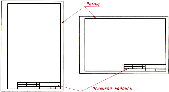 3. Practical work.
I show the construction of the main inscription on the board, and you in the notebooks:1.We build a rectangular inscription: put the length 145mm, height - 22mm. And with the help of a square and a ruler, we draw a horizontal line and then a vertical line.2.Length to the left measure 70mm, draw a vertical line.3.On the left side of the rectangle we measure from above two timesbut by 7 mm,
the same thing is done on the segment, which we carried along the length of 70mm; we draw through these marks two horizontal lines, the first from above - the length of the same 70mm, the second from the top - the length of 145mm, to the end of the outer rectangle. Line from the left to the right.4. We mark the length of the first block on the left-25 mm, and the third right block of 15 mm. We draw vertical lines on the top two graphs. Thus, we obtain two upper blocks of three graphs in each, and the bottom one remains an integer.5. Now in the right lower block measure on the right two times 20mm and hold two vertical lines, dividing the bottom block into three parts.6. The main inscription is ready, now strongly pressing a soft pencil around the ruler. At the intersections, lines must not overlap one another.
3. Practical work.
I show the construction of the main inscription on the board, and you in the notebooks:1.We build a rectangular inscription: put the length 145mm, height - 22mm. And with the help of a square and a ruler, we draw a horizontal line and then a vertical line.2.Length to the left measure 70mm, draw a vertical line.3.On the left side of the rectangle we measure from above two timesbut by 7 mm,
the same thing is done on the segment, which we carried along the length of 70mm; we draw through these marks two horizontal lines, the first from above - the length of the same 70mm, the second from the top - the length of 145mm, to the end of the outer rectangle. Line from the left to the right.4. We mark the length of the first block on the left-25 mm, and the third right block of 15 mm. We draw vertical lines on the top two graphs. Thus, we obtain two upper blocks of three graphs in each, and the bottom one remains an integer.5. Now in the right lower block measure on the right two times 20mm and hold two vertical lines, dividing the bottom block into three parts.6. The main inscription is ready, now strongly pressing a soft pencil around the ruler. At the intersections, lines must not overlap one another. 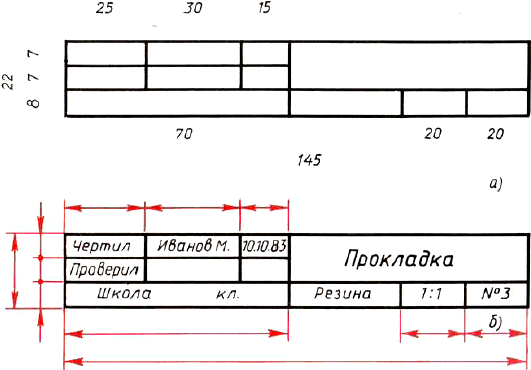 The main inscription is filled with a drawing font, which we will consider in the next lesson.4. CONCLUSION OF LESSONS.
What is called a drawing?
What is the standard? Why is it needed?
What is the format? On the sheets, what format will we work?
HomeworkPrepare and bring correctly sharpened pencils of different hardness, eraser, ruler, squares. Prepare the A4 format of the vertical format by measuring its dimensions and drawing a frame. Run the main inscription on the right, but do not fill it.