TO GAOU SPO "Teachers College of Tambov" METHODICAL INSTRUCTIONS for the implementation of practical works of the discipline "Engineering Graphics" for students of the specialty "280707 Protection in Emergency Situations, Technician-Rescuer" (Works No. 1-6) TAMBOV, 2013 Author: TARASOV VE, Teacher of special disciplines TO GAOU SPO "Teachers' college of Tambov" Reviewer: Lappa TI .. Head of the department "Physical Culture" TO GAOU SPO "Pedagogical College G. Tambova" Methodological instructions for the implementation of practical work in the discipline "Engineering graphics "for students of specialty "280707 Protection emergency rescue techniques" (Works number 1-6) Guidelines for the implementation of graphic work on the course "Engineering Graphics" is designed for students of a specialty 280707 "Protection in emergency situations". The manual contains the necessary theoretical and reference material for the performance of graphic works No. 1- 6. Recommended by the scientific and methodological council of the college as a textbook. INTRODUCTION The program of the course "Engineering Graphics" for students in the specialty of secondary vocational education 280707 Protection in emergency situations, a technician-rescuer determines the amount of knowledge necessary for the implementation of engineering drawings and schemes. Most students work independently, so they are recommended to familiarize themselves with the requirements set by the ESKD standards for the implementation of drawings when studying the engineering graphics course. All graphic work by students should be carried out in accordance with their version on the order number in the training journal. The purpose of this publication is to familiarize students with fonts, lines, methods of constructing conjugations, images of objects, location of species, making cuts, sections and axonometric projections, drawing dimensions and limiting deviations, graphical designation of materials in graphic works and drawing electrical circuits. REQUIREMENTS OF ESKD STANDARDS TO IMPLEMENT GRAPHICS The unified system of design documentation (ESKD) is the most important system of constantly operating technical and organizational requirements ensuring the interchange of design documentation without its re-registration between industries and individual enterprises. It allows to ensure the expansion of unification in the design development of industrial products projects; simplification of forms of documents and reduction of their nomenclature, as well as graphic images: mechanized and automated creation of documentation and, most importantly, the readiness of industry in organizing the production of any product in any enterprise in the shortest possible time. The ESKD presents a set of state standards that establish interrelated common rules and regulations on the procedure for the development and circulation of design documents used by various organizations and enterprises. These uniform rules apply to the training documentation, which can be attributed to the students performing graphic assignments, so all images must be executed accurately, accurately and in accordance with the requirements of ESKD. Assignments are performed on sheets of drawing paper in A3 and A4 format (GOST 2.301-68). After drawing the frame on the sheet in the lower right corner, the sizes of the main job caption, uniform for all formats, are marked. The form of the main inscription is adopted in accordance with the requirements of GOST 2.104-68. Images must be performed in the scale specified in the task, but observing GOST 2.302-68. At filling of the basic and other inscriptions it is required to fulfill the requirements of GOST 2.304-81. When applying dimensions, it is recommended to use GOST 2.307-68. When tracing an image, you should take the thickness of the main lines 0.8 1.0 mm, and the thickness of the remaining lines according to GOST 2. 303-68. LIST OF THE USED LITERATURE 1. Bogolyubov SK The engineering graphics. - M .: Mechanical Engineering, 2004. -352с 2. GOST 2. 303-68. Lines. 3. GOST 2. 304-81. Drawing fonts. 4. GOST 2. 305-68. Images - views, sections, sections. 5. GOST 2. 301-68. Formats // ESKD. General rules for the implementation of drawings. GOST 22.301-68 - GOST 2.321-84. M., 1988. 239 p. 6. GOST 2. 302-68. Scale. 7. GOST 2. 307-68. Drawing of sizes and limiting deviations. 8. Levitsky V.S. Machine-building drawing / В.С. Levitsky. M., 1998. 383 p. 9. Machine-building drawing / G.P. Vyatkin, A.N. Andreeva, A.K. Boltukhin and others. M., 1985. 368 p. 10. Popova G.N. Machine-building drawing / G.N. Popova, S.Yu. Alekseev. SPb, 1999. 453 p. 11. SK Bogolyubov. Individual assignments on the plotting course: Pract. Allowance for students of technical schools. - M .: Higher education. Sc., 1989 - 368 p .: ill. 12. Fedorenko V.A. Handbook of machine-building drawing / V.A. Fedorenko, A.I. Shoshin. L., 1986. 416 p. PRACTICAL WORK No. 1 FILING FORMAT AND PRINCIPAL FOR GRAPHICS AND TEXT DOCUMENTS Purpose: To study graphic formats the types of basic inscriptions in the drawings All drawings must be executed on sheets of paper of standard format. The sizes of the sheets of paper are determined by the dimensions of the outer frame of the drawing (Figure 3). It is carried out by a continuous thin line. The line of the drawing frame is drawn by a solid thick main line at a distance of 5 mm from the outer frame. On the left for the filing leave a field width of 20 mm. The designation and dimensions of the sides of formats are established in GOST 2.304-68. Data on the main formats are given in Table. 1. Table 1 Format designation Dimensions of the sides of the format, mmА0841х1189А1594х841А2420х594А3297х420А4210х297 RULES AND PROCEDURE OF WORK PERFORMANCE The work is carried out in a pencil on a sheet of A3 (297x420) or A4 (210x297) format in accordance with the given sample. The drawing is made with an inner frame (in the form of a solid main line), from the border of the format on the left side, leave a margin for stitching 20 mm, from all other sides - 5 mm. In the lower right corner of the drawing, the main inscription (stamp) is drawn according to GOST 2.104-68 * in accordance with figure 1. We recommend the following filling of the main inscription graphs in the learning process conditions (the standard notation of graphs is preserved): column 1 - name of the part or assembly unit (name topic, on which the task is completed); column 2 - designation of the document according to the system accepted in the college (group name, year, number according to the list, number of the work performed - FSC.31.2011.05.02.); column 3 - designation of the material of the part (fill only in the drawings of the parts); Count 4 - do not fill; column 5 - product mass (do not fill); graph 6 - scale of the image (in accordance with GOST 2.302-68 * and GOST 2.109-73); column 7 - the sequence number of the sheet (on the documents consisting of one sheet, the graph is not filled); column 8 - total number of sheets of the document (the column is filled only on the first sheet of the document); column 9 - the name of the school and the group number; column 10 - the nature of the work performed by the person signing the document, for example: Developed: (student) Checked: (teacher) column 11 - clear spelling of the names of persons who signed the document; column 12 - signatures of persons whose surnames are indicated in column 11; column 13 - the date of signing the document (the month and year are indicated). Fig.1 The text on the drawing field and in the title block is 3.5, 5 or 7 mm in font, and the size numbers are 3.5 or 5 mm. An example of filling the main label is given in Figure 2. The work is done in thin lines, then the final drawing of the drawing is done by lines in accordance with their purpose. The outline is started with dash-dotted and continuous thin lines, then the main solid lines are drawn: first curved sections, then straight lines. ASSIGNMENT: Draw a drawing frame line and a title block on a sheet of A4 drawing paper. PRACTICAL WORK # 2 EXECUTION FONT DRAWING Objective: To study pits of drawing fonts, to get writing skills in drawing font. GOST 2.304-81 establishes drawing fonts, applied to drawings and other technical documents of all industries and construction. The font size determines the height h of uppercase letters in mm. The thickness of the font line d depends on the type and height of the font. GOST sets the following font sizes: (1.8); 2.5; 3.5; 5; 7; 10; 14; 20 (Table 1, 2). The use of font 1.8 is not recommended and is only allowed for type B. The following font types are set: Type A with a slope of 75 ° - d = (1/14) h; Type A without inclination - d = (1/14) h; Type B with a slope of 75 ° - d = (1/10) h; Type B without inclination - d = (1/10) h. Parameters of fonts are given in Tables 1 and 2. Table 1 - Font parameters, mm Font parameters Legend 3,5,5,07,010,014,0ABABABABABHighcase capital lettersh3,53,55,05,07,07,010101414 Height of lowercase letters2,52,53,53,55, 05,07,07,01010Distance between lettersa0,50,70,71,01,01,41,42,022,8Minimum strings pitchb5,56,08,08,511,012,016,017,02224Minimum distance between words1,52,12,13,03,04,24 , 26,06,08,4 The thickness of the font linesd0,250,350,350,50,50,70,71,01,01,4 Table 2 - The width of the letters and numbers of type B, mm Letters and digits The relative size3,55,07,010,014,0 Written lettersB, B, D, K, L, H, O, P, P, T, U, C, L, L, E, H, 6d23469A, D, M, X, N, U7d2.53.55711, , B8d345.5812E, Г, З, С5d1.82.53.557 The capital letters А, б, в, г, д, е, з, и, d, к, л, н, о, п, р, у, х, ч, d, d, e, d5d1.82.53.557m, d, s, w6d23469g, t, f, w, w7d2.53.55711c4d1.62346Digits 2, 3, 5, 6, 7, 8, 9, 05d1.82.53,55713d11.523446d23469 THE TASK. Font size 10 type B to write the letters shown in the alphabet (lowercase and uppercase), numbers from 0 to 10 and two any words. The sample of the task is shown in Figure 1. NOTES ON THE JOB IMPLEMENTATION First, you need to prepare a sheet of paper of standard A4 format with a frame 5 mm from the top, to the right and bottom and 20 mm to the left. The sequence of the task of writing a standard type B font of size 10 is as follows: - Conduct all the auxiliary horizontal straight lines defining the boundaries of the lines of the font; - lay the distance between the lines, equal to 15 mm; - postpone the height of the font h, i.e. 10 mm; - postpone segments that are equal to the width of the letters plus the distance between the letters; - conduct inclined lines for the grid at an angle of 75 ° using two triangles: with an angle of 45 ° and with angles of 30 ° and 60 °. Example of a task assignment PRACTICAL WORK No. 3 DRAWING LINES Objective: to obtain skills in drawing lines and using drawing tools All drawings are made with lines of various purposes, shapes and thicknesses (Table 3). The thickness of the lines depends on the size, complexity and purpose of the drawing. According to GOST 2.303-68, lines of various types are used to depict products in drawings, depending on their purpose, which helps to identify the shape of the displayed product. Table 1 - Line types Inscription Thickness of the line with respect to the thickness of the main line. Name Usage The thick thick main line is made by the thickness denoted by the letter s, ranging from 0.5 to 1.4 mm, depending on the complexity and magnitude of the image in this drawing, and also on the format drawing. The solid thick line is used to represent the visible contour of the object, the contour of the outlined section, and the part of the cut. s / 3-s / 2 Solid thin line is used to display dimension and extension lines, hatching of sections, contour line of superimposed section, line-leader, line for the image of boundary details ("situation"). s / 3-s / 2 Solid wavy line applied for displaying break lines, line of demarcation of the view and cuts / 3-s / 2 The dashed line is used to display the invisible contour. The length of the strokes should be the same. The length should be chosen, depending on the size of the image, from about 2 to 8 mm, the distance between the strokes is 1 ... 2 mm.s / 3-s / 2 The dash-dotted thin line is used to represent the axial and centrelines, the section lines being the axes of symmetry for superimposed or rendered sections. The length of the strokes should be the same and selected depending on the image size, approximately 5 to 30 mm. The distance between the strokes is recommended to take 2 ... 3 mm.s / 2-2s / 3. The dash-dot thickened line is used to display elements located in front of the cutting plane ("superimposed projection"), lines indicating surfaces to be heat treated or coated. -s / 2The open line is used to indicate the section line. The length of the strokes is taken as 8 ... 20 mm depending on the image size. S / 3-s / 2 Solid thin with fractures the line is used for long lines of breakage. S / 3-s / 2 The dashed double-dot line is used to show details in extreme or intermediate positions; Bend lines on scans The quality of the drawing depends largely on the quality and setting up of tools, as well as on the care of them. Drawing tools and accessories must be kept in good order. After work, tools should be wiped and cleaned in a dry place. This prevents the warping of wooden tools and the corrosion of metal. Before work, you should wash your hands and wipe the squares and the vortex with a soft rubber band. Pencils. Accuracy and accuracy of the drawing largely depend on the correct sharpening of the pencil. Sharpening graphite can be done with a grinding skins. The student must have three pencil marks: M-B, TM-HB and T-H. When drawing drawings with thin lines, it is recommended to use a pencil of the T-mark. The drawing lines should be drawn with a pencil of TM or M in the drawing. The compass mark M should be inserted into the compass. The circular compasses are used for drawing circles. In one leg of the compass insert the needle and fix it with a screw, and in the other - a pencil insert. To measure the dimensions and postpone them in the drawing, an insert with a needle is used. Calipers are used to draw circles of small diameter (from 0.5 to 10 mm). Rotating leg for ease of use freely moves along the axis of the calipers. When drawing circles of large radii in the leg of the compass insert an extension cord in which the pencil insert is fixed. The lines are applied in a certain direction: Horizontal lines are drawn from left to right, vertical lines are drawn from the bottom up, circles and curves are clockwise. The center of the circle must always be at the intersection of the lines of the axial and center lines. Hatching in the drawings is performed in the form of parallel lines at an angle of 45 ° to the centerline or to the line of the contour adopted as the main one. The slope of the hatch lines can be either left or right. Two adjoining figures hatch in different directions. If there is a third adjacent to the two adjoining figures, then it is possible to diversify the hatching by increasing or decreasing the distance between the lines of hatching. Non-metallic materials, including fibrous monolithic and plate (pressed) in sections cross in a cage. ASSIGNMENT: Draw drawn lines and images (according to the variant of the task figure 1, 2), observing their specified location. The thickness of the lines should be in accordance with GOST 2.303 - 68, do not apply dimensions. The task is carried out on a sheet of drawing paper in A4 format. INSTRUCTIONS FOR THE JOB IMPLEMENTATION It is more convenient to start the task by drawing a thin vertical line through the middle of the inner frame of the drawing, where you make notes in accordance with the dimensions given in the task. Through the planned points, thin secondary horizontal lines are made to facilitate the graphic part of the task. On vertical axes intended for circles, points are drawn through which the circles are drawn by the lines indicated in the job. In the training drawings, a solid, thick main line is usually made with a thickness of s = 0.8 ... 1 mm. Figure 1 - even numbers of options Figure 2- odd numbered options PRACTICAL WORK No. 4 PERFORMING DRAWING OF DETAILS WITH CONNECTIONS Objective: to study the execution of conjugations of curves, to draw a drawing of a part with conjugations 1. Division of circles into equal parts Division of circle 4 and 8 of equal parts 1) Two mutual perpendiculars of the diameter of the circle divide it into 4 equal parts (points 1, 3, 5, 7). 2) Next divide the right angle into 2 equal parts (points 2, 4, 6, 8) (Figure 1 a). Division of a circle into 3, 6, 12 equal parts 1) To find points dividing a circle of radius R into 3 equal parts, it is sufficient to draw an arc with radius R. from point 2 (1), from any point of the circle, for example point A (1) (Figure 1 b). 2) We describe the arcs R from points 1 and 4 (Fig. 1c). 3) Describe the arcs 4 times from points 1, 4, 7, 10 (Figure 1 g). abw where Figure 1 - Division of circles into equal parts a - into 8 parts; b - into 3 parts; в - on 6 parts; г - on 12 parts; d - 5 parts; e - in 7 parts. Divide the circle by 5, 7, equal parts 1) From the point A with radius R, draw an arc that intersects the circle at the point n. From point n, drop the perpendicular to the horizontal center line, get the point C. From point C with radius R1 = C1, draw an arc that intersects the horizontal center line at point m. From point 1 of radius R2 = 1m, draw an arc that intersects the circle at point 2. The arc 12 = 1/5 of the circumference. The points 3,4,5 are found by laying off the segments equal to m1 by the compass (Figure 1 d). 2) From the point A we draw an auxiliary arc of radius R, which intersects the circle at the point n. From it we lower the perpendicular to the horizontal center line. From point 1 of radius R = nc, make seven notches around the circle and get 7 desired points (Figure 1 e). 2. Constructing conjugations A conjugation is a smooth transition of one line to another. For accurate and correct execution of drawings it is necessary to be able to perform construction of couplings that are based on two positions: 1. For the conjugation of a straight line and an arc, it is necessary that the center of the circle to which the arc belongs lies on the perpendicular to the straight line reconstructed from the point of conjugation (Figure 2a ). 2. For the conjugation of two arcs, it is necessary that the centers of the circles to which the arcs belong lie on a straight line passing through the conjugation point (Figure 2b). Figure 2 - Provisions on conjugations a - for a straight line and an arc; b for two arcs. Conjunction of two sides of an angle by an arc of a circle and a given radius. Conjunction of two sides of an angle (acute or blunt) by an arc of a given radius is performed as follows: In parallel to the sides of the corner, two auxiliary straight lines are drawn at a distance equal to the radius of the arc R (Fig. 3a, b). The point of intersection of these lines (point O) will be the center of an arc of radius R, i.e. center of conjugation. From the center O describe an arc, smoothly passing into straight lines - the sides of the angle. The arc ends at the junction points n and n1, which are the bases of the perpendiculars dropped from the center O to the sides of the angle. When constructing the conjugation of the sides of a right angle, the center of the arc of the conjugation is easier to find with the aid of a compass (Figure 3c). From the vertex of the angle A we draw an arc of radius R equal to the conjugation radius. On the sides of the corner get the conjugation points n and n1. From these points, as from the centers, draw arcs of radius R to the intersection at the point O, which is the center of conjugation. From the center O describe the conjugate arc. Figure 3 - Conjugation of angles a - acute; b - stupid; in - direct. Conjunction of a straight line with an arc of a circle The conjugation of a straight line with an arc of a circle can be performed using an arc with an internal touch (Fig. 4b) and arcs with an external touch (Fig. 4a). To construct the conjugation by an external tangency, draw a circle of radius R and a straight line AB. Parallel to the given line at a distance equal to the radius r (the radius of the conjugate arc), draw a straight line ab. From center O, draw an arc of a circle with a radius equal to the sum of the radii R and r, until it intersects the line ab at the point O1. The point O1 is the center of the conjugation arc. The conjugation point c is found at the intersection of the straight line OO1 with an arc of a circle of radius R. The conjugation point C1 is the base of the perpendicular dropped from the center O1 to the given line AB. With the help of similar constructions, the points O2, C2, C3 can be found. In Figure 6b, conjugate an arc of radius R with a line AB of an arc of radius r with inner tangency. The center of the conjugation arc O1 is at the intersection of the auxiliary line drawn parallel to the given line at a distance r, with the arc of the auxiliary circle described from the center O with a radius equal to the difference R-r. The conjugation point is the base of the perpendicular dropped from the point O1 to the given line. The conjugation point c is found at the intersection of the straight line OO1 with the conjugate arc. ab Figure 4 - Coupling of the arc with the straight line a - with an external touch; b - with an inner touch. Matching an arc with an arc The conjugation of two arcs of circles can be internal, external, and mixed. With internal conjugation, the centers O and O1 of the conjugate arcs are located inside the conjugate arc of radius R (Fig. 5a). When the conjugate arcs are conjugate, the radii R1 and R2 are outside the conjugate arc of radius R (Fig. 5b). With mixed conjugation, the center O1 of one of the conjugate arcs lies inside the conjugate arc of radius R, and the center O of the other conjugate arc is outside of it (Figure 5c). abv Figure 5 - Coupling arcs a - internal; b - external; c - mixed. When plotting contours of complex parts, it is important to be able to recognize in certain smooth transitions certain types of interfaces and to be able to draw them. To acquire skills in constructing conjugations, exercises are carried out for plotting contours of complex parts. To do this, you need to determine the order of the construction of interfaces and only then proceed to implement them. ASSIGNMENT: Draw the images of the contours of the parts indicated in the task drawing, to make dimensions. The task is done on a sheet of drawing paper in A4 format. Instructions for completing the task When performing each task, a certain sequence of geometrical constructions must be observed: - axial, center lines, basic descriptive; - arcs, rounding; - stroke, hatching, extension lines; - dimensions. Variants of assignment PRACTICAL WORK № 5 IMPLEMENTATION OF TYPES ON THE AXONOMETRIC IMAGE OF THE DETAILS Objective: to obtain skills in the construction of projections of the model of the part. ASSIGNMENT: to construct three kinds of details on this pictorial image in the axonometric projection in accordance with the variant of the task. The task is carried out on sheets of drawing paper in A3 or A2 format (GOST 2.301-68). After drawing the frame on the sheet in the lower right corner, the sizes of the main job caption, uniform for all formats, are marked. The form of the main inscription is adopted in accordance with the requirements of GOST 2.104-68. Images should be performed on a scale if necessary, GOST 2.302-68. At filling of the basic and other inscriptions it is required to fulfill the requirements of GOST 2.304-81. When applying dimensions, it is recommended to use GOST 2.307-68. When tracing an image, you should take the thickness of the main lines 0.8 1.0 mm, and the thickness of the remaining lines according to GOST 2. 303-68 (ST SEV 1178-78). The objects in the technical drawings are represented by the method of rectangular projection onto six faces of a hollow cube. It is assumed that the object being represented is located between the observer and the corresponding face of the cube (see Fig. 1). The edges of the cube are taken as the main projection planes. There are six main projection planes: two front planes-1 and 6 (front view or main view, rear view), two horizontal planes -2 and 5 (top view and bottom view), two profile planes -3 and 4 (left view and right view) . The basic planes of projections are combined in one plane together with the images obtained on them. The image on the frontal plane of the projections is adopted in the drawing as the main one. The object is positioned relative to the frontal plane of the projections so that the image on it - the main image - gives the most complete picture of the shape and size of the object. Objects should be displayed in a functional position or in a position convenient for their manufacture. Items consisting of several parts should be displayed in a functional position. The question of which of the main species should be used in the drawing of the product must be solved so that, with the smallest number of species combined with other images (local and additional views, sections and cross-sections, remote elements), the drawing fully reflects the design of the product. The order of the task: 1) to study GOST 2.305-68, 2.307-68; 2) carefully familiarize yourself with the construction of the figure by its graphic representation and determine the main geometric bodies from which it consists; 3) to allocate on the sheet of paper the corresponding area for each kind of detail; 4) apply thinly in pencil all the lines of the visible and invisible contour, mentally dividing the detail into the main geometric bodies; 5) apply all the necessary remote and dimensional lines; 6) to put the dimensional numbers in the drawing; 7) fill in the main inscriptions and verify the correctness of all the constructions; 8) draw a drawing with a pencil. Variants of the task PRACTICAL WORK № 6 IMPLEMENTATION OF THE TECHNICAL DRAWING OF A SIMPLE DETAIL A technical drawing is a pictorial image that possesses the basic properties of axonometric projections or perspective drawing, executed without the use of drawing instruments, on the eye-scale scale, in accordance with proportions and possible shading of the form. Technical drawing can be performed using the method of central projection, and thereby obtain a perspective image of the object, or a method of parallel projection (axonometric projections), constructing a visual image without perspective distortion. The technical drawing can be performed without detecting the volume by shading, with a tint of volume, and also with the transfer of color and material of the depicted object. In technical drawings it is allowed to reveal the volume of objects by the methods of shading (parallel strokes), scraping (strokes applied in the form of a grid), and dotted shading. The most commonly used method for detecting the volume of objects is the chateau. It is generally believed that the rays of light fall on the object from above on the left. Illuminated surfaces are not shaded, and shaded surfaces are covered with shading (dots). When hatching shaded places, dashes (dots) are applied with the smallest distance between them, which allows you to get a denser shading (dotted shade) and thereby show shadows on objects. 1. Technical drawings showing the volume of the shading (a), the shuffle (b) and the dot shade (e) Table 1. Shading of the shape of the shading techniques Technical drawings are not metrically defined images unless they are marked with a measures. An example of constructing a technical drawing in a rectangular isometric projection (isometry) with a distortion coefficient of all axes equal to 1. When the true dimensions of the part along the axes are deposited, the figure is 1.22 times larger than the real part. Methods for constructing an isometric projection of a part: 1. The method of constructing an isometric projection of a part from a shaping face is used for parts whose shape has a planar face, called the form-forming face; the width (thickness) of the part is the same all over, and there are no grooves, holes and other elements on the lateral surfaces. The sequence of constructing the isometric projection consists in the following: * construction of the axes of the isometric projection; * construction of an isometric projection of the shaping face; * construction of projections of other faces by means of image of model edges; The outline isometric projection (Figure 1). Fig. 1. Constructing an isometric projection of a part starting from a shaping face 2. The method of constructing an isometric projection based on the successive removal of volumes is used in those cases when the displayed form is obtained as a result of removing any volumes from the initial form (Fig. 2). 3. The method of constructing an isometric projection based on a sequential increment (addition) of volumes is used to perform an isometric image of a part whose shape is derived from several volumes connected in a certain way to each other (Figure 3). 4. The combined method of constructing an isometric projection. The isometric projection of a part, the shape of which is obtained as a result of a combination of different forming methods, is performed using a combined construction method (Fig. 4). Axonometric projection of the part can be performed with the image (Fig.5, a) and without the image (Fig.5, b) of the invisible parts of the form. Fig. 2. Construction of an isometric projection of a part based on successive removal of volumes Fig. 3. Construction of an isometric projection of a part based on a sequential increment of volumes Fig. 4. Using the combined method of constructing an isometric projection of a component Fig. 5. Variants of the image of isometric projections of a detail: a - with the image of invisible parts; b - without the image of invisible parts. ASSIGNMENT: in accordance with the variant of the task and the dimensions of the part, construct a technical drawing on a format A4 of checkered paper in a rectangular isometric projection. Job Options Option 1-2-3 Option 4-5-6 Option 7-8-9 Option 10-11-12 Option 13-14-15 Option 16-17-18 Option 19-20-21 Option 22-23-24 -25 1
1. Construction of flat curves and conjugations
2. Projection drawing (the construction of three types of this pictorial image of the subject).
3. Dimetry, the construction of the three main types and the dimetry of the detail by its description.
4. The construction of three images of two given. Section and sections.
5. Axonometry
6. Construction of cut lines.
7. Threaded (bolt, screw, hairpin, thread) and all-in-one connections;
8. Fasteners;
9. Teeth transmission (cylindrical, conical, worm, rack).
10. Assembly drawings. products. Compilation and reading of the assembly drawing. Specifications.
11. Detailing of assembly drawings (Bogolyubov)

Examples of examinations for universities

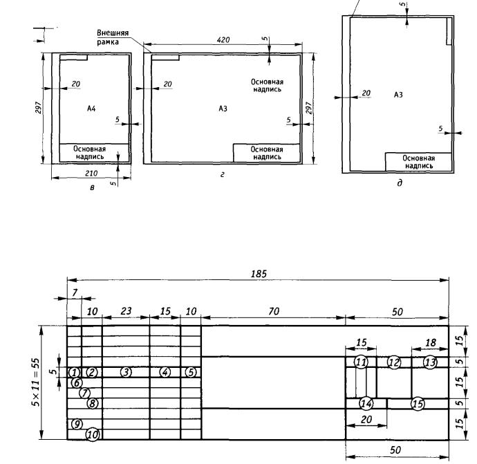
How to fill out the stamp (main inscription) on the drawing
![]()
In the columns ( numbers graph see in figure in brackets) title block indicate:
(1) - the name of the product or its component parts;
(2) - designation of a technical document on GOST 2.201 - 80;
(3) - symbol for the material (only for parts drawings);
(4) - a letter (for example, " Have"), Begin to be filled from the leftmost cell sequentially. Literature "U" means "educational";
(5) - mass of the product or parts thereof ( GOST 2.109 - 73 *);
(6) - scale of the image of the object on the drawing;
(7) - the sequence number of the sheet (if the drawing is executed on one sheet, the graph is not filled);
(8) - the total number of sheets of the drawing of this product (only on the first sheet);
(9) - the name of the enterprise, educational institution or department that issued this drawing;
(10) - the nature of the work performed by the signer;
(11) - the names of the signatories;
(12) - signatures;
(13) - the date of signing the document;
(14 - 18) - information on changes in the drawings.
Contact form for ordering drawings
With this contact form, you can easily to orderengineering drawings . Deadline control works on drafting and engineering work schedule - 1-4 days, at medium volumes. If you provide the necessary information, I fill out your stampson the drawings. I not an intermediary, I do all the work myself. At present, I do not carry out drawings in a pencil, only in digital form, in the Compass (AutoCAD).
MINISTRY OF EDUCATION AND SCIENCE OF THE RUSSIAN ASSOCIATION "SIBERIAN TECHNOLOGICAL UNIVERSITY"
FGOU SPO "BURYATSKY FOREST INDUSTRIAL COLLEGE"
ENGINEERING GRAPHICS
METHODICAL INSTRUCTIONS to the study of the course and the performance of control tasks
for students of correspondence students of specialty 270103 "Construction and operation of buildings and structures"
Ulan-Ude, 2013
Methodical instructions for studying the course and fulfilling the control tasks on the engineering schedule for students of external students - Ulan-Ude: 2013.
Specialties 270103 Building and operation of buildings and structures
Engineering Graphics
I.T. Bubeyev Ph.D., senior lecturer of the chair of the ICG SSSUTU
L.Yu. Prudova Associate Professor of the Department of the ICG SSSUTU
I.I. Astapkovich manager. Department of Engineering Graphics
Sib State Technical University
The guidelines give recommendations for studying program material, questions for self-control, examples of solutions to typical tasks, recommendations for the implementation of tests, assignments for testing. They are designed to assist students in specialty 270103 "Construction and operation of buildings and structures" in organizing their independent work on the study of the discipline "Engineering Graphics".
O.P. Bortsova, 2013
Introduction ............................................................................... 4 Section I. General requirements ...................................................... 4 Recommendations for the implementation of drawings and organization
workplace ......................................................... ... 5 Section II. Instructions for studying the course ................................................................ 6 Thematic plan ........................................ ................ 6 Methodological guidelines for studying the topics .................................. 7 Section III. Instructions for the execution of test works ............... ... .... 17 Test work No. 1 ................................................................ ............ ... 17 Test work No. 2 ............................................. .... 29
Section IV. Tasks for control work and samples of their design .... 33 Test work No. 1 ................................ ............ ... 33 Test work No. 2 ........................... ............... .. ... .. 46 References .... ...................................................................... .... 55
Introduction
The purpose of studying the discipline of "Engineering Graphics" is to assimilate the students knowledge and skills necessary for the execution and reading of drawings.
As a result of studying the discipline, the student must:
have an idea:
about the state standards of ESKD and SPDS, the conventionality of the image on the drawings;
about methods of designing;
on international standards for the design of building drawings;
laws, methods and techniques of projective drawing and descriptive geometry;
requirements of the state standards of ESKD and SPDS for registration and
drawing up of construction drawings;
to use the normative documentation when solving the problems of drawing up construction drawings;
perform construction drawings in the technique of manual and computer graphics;
When studying the material, it is necessary to observe the unity of terminology, designations, units of measurement in accordance with the applicable GOSTs and SNiPs.
Section I. General Requirements
For this discipline, two home control works covering all sections of the curriculum are envisaged. Performance of control works determines the degree of mastering by the students of the studied material and the ability to apply the knowledge gained in solving practical problems in accordance with the requirements of ESKD and SPDS.
familiarization with the thematic plan and methodical instructions on the topics;
studying of state standards and program material on recommended literature;
exercise to consolidate theoretical material;
the preparation of answers to questions of self-control, given after each topic;
performance of test work.
When studying the educational material, it is necessary to keep notes, perform exercises, answer questions in the workbook.
The drawings of the test papers must be stitched into an album with A4 format files (297x420) with the title page. Format A3 folded in half.
In the event of difficulties in fulfilling the tasks, the student should seek advice from the college.
Poorly executed control work needs to be corrected, depending on the instructor's instructions.
For quick, accurate execution of drawings, getting satisfaction from the results of one's work, it is necessary to have: drawing board 7 (see Fig. 1), flight 1, set of drawing tools and accessories, use special drawing paper 6 (sheets of paper A4A and FA3). The basic drawing tools in the form of a set are placed in the cabinet 10. A scale measuring ruler 5 is needed with a uniform scale along the edges with a division price of 1 mm, angles 2 with angles of 30.60.900, and angles of 45.45.900. A set of pencils of different hardness: T (H) - solid; TM (HB, F) - medium hardness; M (B) - soft, the lead in circulation 18 should be soft. To remove auxiliary and erroneously drawn lines in the drawing, soft elastic bands (eraser) are used. 3, protractor 25, different stencils 23, 24 facilitate and accelerate the process of drawing.
Fig. 1. Drawing tools and devices
Section II. Instructions for studying the course.
Thematic plan
Sections and Themes | |||
Section 1. General rules for drawing up drawings | |||
Formats. Main frame and title block | |||
Fonts for drawing | |||
Drawing Lines | |||
Scale. Dimensioning | |||
Graphic techniques for performing images | |||
Computer graphics | |||
Section 2. Fundamentals of Descriptive Geometry | |||
and projection drawing | |||
Methods of projection | |||
Orthogonal projection of a point, a line, a plane | |||
Converting a drawing to determine the actual values | |||
Mutual intersection of planes | |||
Intersection of a straight line with a plane | |||
Axonometric Projections | |||
Geometric bodies | |||
Crossing of bodies by planes | |||
The intersection of a straight line with the surface of geometric bodies | |||
Mutual intersection of body surfaces | |||
Drawings of models | |||
Section 3. Fundamentals of technical drawing | |||
Images | |||
Thread and its image in the drawings | |||
Detachable and non-detachable connections | |||
Technical drawing | |||
Section 4. Features of registration of building drawings | |||
General information on construction drawings | |||
Features of the requirements for graphic design | |||
construction drawings | |||
Conditional graphics and images | |||
Section 5. Construction drawings | |||
General Provisions | |||
Methodical instructions for studying topics Goals and objectives of the academic discipline "Engineering Graphics" When studying the topic, it is necessary to understand the goals and objectives of Engineering Graphic as a learning discipline, to study the documentation, to become acquainted with tools and accessories for performing graphic works (Fig. 1). Questions for self-control 1. What is "standardization", "standard"? 2. What are the categories of standards? 3. What is ESKD, SPDS and SNiP? 4. What is the role and tasks of the discipline "Engineering Graphics"? 5. What tools and accessories do I need to use when I make a drawing? Section 1. GENERAL RULES FOR DESIGNATION OF DRAWINGS Topic 1.1. Formats. Main frame and title block When studying the topic, it is necessary to master the principle of obtaining the main formats (GOST 2.301-68 *), their sizes and designations (Fig. 2), consider the following issues: a preliminary frame; main drawing frame; the main inscription, its graphs and dimensions in accordance with GOST 2.104-06 * and GOST 21.101-97 (Fig. 3), filling in the column in accordance with the version approved by the BLPK (see examples of graphic design). Fig. 2 a, b Formats basic (a) and additional (b)
Fig. 2 in, d, d. Formatting for drawing jobs Fig. 3. The shape and dimensions of the main inscription according to GOST 2.104-2006: 1-15 - words in the cells of the main inscription, including in abbreviated form: 1 - Change. (changes); 2 - Sheet; 3 - No. of documents. (Document number); 4 - Sign. (signature); 5 - Date; 6 - Developed. (developed); 7 - Prov. (checked); 8 - T. counter. (technical control); 9 - N. Kontr. (norm-control); 10 - Approved. (approved); 11 - Lit. (lit.); 12 - Weight; 13 - Scale; 14 - Sheet; 15 - Sheets. Questions for self-control 1. How are basic formats formed and denoted? 2. What are the sizes of A4, A3, A2 and A1 formats? 3. How far from the edge of the format is the drawing frame drawn? 4. How is the main lettering on A4, A3? 5. What is the content of the title block? 8 - Topic 1.2. Fonts for drawing Questions for self-control 1. What types of fonts sets GOST 2.304–81? 2. What is called the font size? 3. What is the difference between lowercase and uppercase letters? 4. What is the ratio of the width of the letter, the thickness of the font line and its height? Topic 1.3. Drawing Lines When studying the topic, you should learn the meaning of the line for reading the drawing, the name of the lines, their purpose, outlines, proportional thickness ratio. Questions for self-control 1. What is the purpose of the drawing lines? 2. In what limits is the thickness of the continuous main line chosen? 3. What is the purpose of a continuous thin line and its thickness? 4. What is the purpose of the wavy line and its thickness? 5. What is the thickness of the broken line? 6. What is the purpose and thickness of the dash-dot line? Topic 1.4. Scale. Dimensioning When studying the topic, it is necessary to be guided by GOST 2.302-68 *. ESKD. Scale. Questions for self-control 1. What is called scale? 2. What are the standard scales and the number of the corresponding GOST? 3. At what distance should you draw dimensional lines from the contour lines and between parallel dimension lines? 4. How is the extension line in relation to the dimension line? 5. What signs accompany the dimensions of diameter, radius, slope and taper? Topic 1.5. Graphic techniques for performing images It is recommended to study the topic in the following sequence: interrelation of mathematical positions and methods of graphic constructions; graphical techniques for dividing a segment, circles (Fig. 7a), angles (Fig. 7b); conducting parallel and perpendicular straight lines; the construction of a rectangle equal to the given one; Straight, tangent to the circle (Fig. 8); conjugation (Fig. 9, 10); slope, taper and their designation in the drawings; circular curves (box, oval, etc.); the local curves (ellipse, hyperbola, parabola, etc.) - (Fig. 12-16); methods of working with the tool "templates" - (Fig.11).
Questions for self-control 1. How to divide a circle into 3, 4, 5, 6 equal parts in geometric ways? 2. How to divide a circle into any number of parts? 3. In which cases is pairing used? 4. How to pair, in what order? 5. How do the gradient and taper in the drawings? 6. What are the curved curves? Topic 1.6. Computer graphics When studying the topic, you should familiarize yourself with the possibilities of obtaining clear copies of drawings on a personal computer through a printer or plotter. Questions for self-control 1. How do you know the possibilities of using computers to perform graphic work? Section 2. BASICS OF THE SCIENTIFIC GEOMETRY AND PROJECT SCATTERING Topic 2.1. Methods of projection When studying the topic, it is necessary to understand the terminology of the projection process, to understand the difference between central and parallel projection. Questions for self-control 1. What is the method of projection? 2. What is the difference between central and parallel projection? 3. Which projections are called rectangular? Topic 2.2. Orthogonal projection of a point, a line, a plane When studying a topic for better mastering of the material, it is necessary to solve the problems of constructing the projections of a point, a line, a plane and their mutual arrangement. Questions for self-control 1. What position does the point in space occupy if its frontal projection lies on the axis of the projections? 2. At what position is a straight line, one of its projections is a point? 3. When is the length of the projection of a line segment equal to the length of a segment? 4. How are parallel straight lines drawn in the drawing? 5. How can a flat figure be specified in the drawing? 6. How to determine the point of intersection of a straight line with a plane? 7. Under what conditions does the line belong to the plane? Topic 2.3. Converting a drawing to determine the actual values When studying the topic, the following questions should be learned: projecting onto an additional plane of projections; Use the projection method on additional planes to determine the actual values of the segments and |