Subject 6. Build. Detailing. Fragments. Creating electrical schematic diagrams.
Modes of work with the library
You can set the desired mode by selecting the appropriate option in the properties dialog of the library being added.
KOMPAS-3D provides four different modes of operation with the connected library - window, dialogue, menu and panel. In each case, the mode of operation is selected by the user for reasons of convenience. Switching the operation mode with the library can be performed at any time, even during the execution of a library function.
In mode menu The library structure is displayed as a standard hierarchical menu.
If set to dialogue , there is a dialog box on the screen, in the left part of which a list of commands of the current library is displayed. Commands can be grouped by sections. The right side of the dialog displays slides that make it easier to find the right command.
To return to the usual work with the system, it is necessary to complete the dialogue of the library.
In mode window The library structure is displayed in a standard Windows window. You can resize the library window, as well as minimize (minimize) it, leaving only the icon on the screen. The main advantage of the window mode is that, unlike the menu and dialogue modes, the library and the main system operate simultaneously. You can dynamically switch from the main system commands to library functions and vice versa.
In mode panels The library structure is presented on a separate tab in the Library Manager window. You can resize any tab area. The advantage of the panel mode is the ability to view slides corresponding to the library commands. As in the window mode, the library and the main system operate simultaneously.
Assembly drawing - document containing the image of the assembly unit and other data necessary for assembly (manufacturing) and control. The basic requirements for the implementation of assembly drawings establishes GOST 2.109-73.
Assembly drawing must contain:
1) an image of the assembly unit, giving an idea of the location and interconnection of the component parts connected according to this drawing;
2) information that provides the possibility of assembling and controlling the assembly unit;
3) dimensions, maximum deviations and other parameters and requirements that must be monitored or performed according to the assembly drawing;
4) indications of the nature of the pairing and methods of its implementation, if the accuracy of the pairing is ensured during assembly (selection of parts, their fitting, etc.);
5) instructions on the method of making permanent connections (welded, brazed, etc.);
6) item numbers of components included in the product;
7) the main characteristics of the product;
8) overall dimensions defining the limiting external or internal outlines of the product;
9) installation dimensions, according to which the product is installed at the installation site;
10) connecting dimensions, according to which the product joins other products;
11) required reference dimensions.
All components in the assembly drawing number according to the item numbers specified in the specification. Position numbers indicate on the shelves of leader lines drawn from images of visible parts.
The leader line that crosses the image contour and is not retracted from any line ends with a full stop. The callout line, retracted from the lines of the visible and invisible contour, as well as from the lines denoting the surface, end with an arrow.
Leader-lines must: do not intersect each other, be non-parallel to the hatching lines (if the leader line goes along the shaded field) and not intersect, as far as possible, the dimension lines and elements of the image that do not contain the inscription on the shelf.
Position numbers indicate on those images in which the corresponding component parts are projected as visible, as a rule, on the main views and the sections replacing them.
The position numbers are arranged parallel to the main inscription of the drawing outside the contour of the image and grouped into a column or row, if possible, on the same line.
Item numbers in the drawing are usually applied once. It is allowed to re-specify the position numbers of the same components.
The font size of the position numbers must be one to two numbers larger than the font size h adopted for the dimension numbers in the same drawing.
For a group of fasteners belonging to the same attachment point, you can make a common leader line with vertical position numbers.
Assembly drawings are carried out, as a rule, with simplifications, corresponding to the requirements of ESKD standards.
Not allowed to be shown on assembly drawings:
Chamfers, roundings, grooves, recesses, protrusions and other small elements;
The gaps between the core and the hole;
Covers, housings, partitions, etc., if it is necessary to show the component parts of the product covered by them. In this case, make the appropriate inscription, for example: "The cover of pos. 3 is not shown";
The inscriptions on the plates, corporate slats, scales and other similar details, depicting only their contour.
Assembly drawing is performed in the following sequence:
1) select the number of images;
2) the choice of scale images;
3) selection of paper format;
4) image layout;
5) the execution of images;
6) drawing sizes;
7) drawing numbers of positions;
8) the implementation of textual material;
9) filling in the main inscription.
The technical requirements in the drawing set forth, grouping together the requirements that are homogeneous and similar in nature, possibly in the sequence recommended by GOST 2.315-68.
Creating an assembly drawing involves several steps:
First stage - opening of all documents that contain parts included in the assembly drawing. Let's say we want to create an assembly drawing Roller and Sleeve, details for which are created in advance. For this:
Standard by button Open - second from the left - or press the key combination Ctrl + O.A dialog box will appear. Select a file to open;
Find the required file, for example, named Drawing_rolick.cdw. In it, we previously saved the drawing roller;
Click on its name with the mouse. The file window will appear in the viewport on the right - drawing roller. Then click the button. Open. The selected file will appear on the screen;
Do the same with another previously created file called Drawing_Button. The selected file will appear on the screen;
Window Mosaic upright. The selected drawings will appear, which will be placed in a vertical mosaic.
You can also select all the necessary files first while holding down Ctrl, and then click on the button Open. All selected files will open, and their contents will be placed in the form of a vertical mosaic on the screen.
However, the called images may not be located in the center of their window. Of all the documents called, only one will be active. To change the layout of a drawing:
Click on the window in which the drawing is located off-center. The window is activated;
Click on the toolbar View by button show all - with the image of the drawing, the penultimate on the panel. In the active window, the drawing will be installed in the center;
Click on another window to select it, and then click on the button. show all. In this window, the drawing will also be installed in the center, etc.
In our example, it will look like the one shown in fig. 6.1.
Fig. 6.1. Submission of parts before creating an assembly drawing Roller + Sleeve
Second phase - creation of a new document with a base detail with oversize and roughness designations removed. For this:
Click on the window Drawing roller, if this window is not activated, i.e. not current;
Click on the item in the main menu. Fileand then in the drop-down menu - by item Save as. A dialog box will appear. Name the file to write; Enter in the dialog box File name: the name of the new document, for example, C_dating or PK.02.06.01.00.CDW;
Click on the button in the file window Expand - the middle of the three located in the upper right corner of the current window; increase the image of the roller in full screen and remove all unnecessary dimensions and roughness symbols.
To remove an extra object in the drawing:
Increase the area where the extra object is located;
Click on it with the mouse to select it. The object is highlighted in green;
Press the key Delete. The selected object will disappear from the screen.
After removing all unnecessary dimensions and roughness marks, the base detail Roller will look as shown in fig. 6.2.
Fig. 6.2. Representation of a roller with oversize and roughness designations removed
Third stage - transfer the sleeve geometry to the roller assembly drawing window. For this:
Click on the item in the main menu. Window, and then - by the name of the file containing the part Sleeve. A working drawing of the sleeve appears on the screen;
Click on the toolbar View on the first button - Zoom in frame;
Click on the location of the starting point of the rectangular frame (upper left corner);
Move the mouse pointer to the location of the end point of the rectangular frame (lower right corner) and click. There will be an increase in the sleeve. Increasing the size of the sleeve can be done with the mouse wheel.
Remove unnecessary part objects. This is primarily a sign of roughness and axial line. For this:
Press the key Ctrl and, holding it, click on the axis of symmetry, and then - on the sign of roughness. Specified objects are highlighted in green;
Press the key Delete. Selected objects will disappear from the drawing.
Remaining objects can be deleted using the frame selection. For this:
Click on the item in the main menu. Highlightand then in the dropdown menu - on the item Frame;
Click on the location of the starting point of the rectangular frame (upper left corner);
Move the mouse pointer to the location of the end point of the rectangular frame (lower right corner) and click. The selection frame should be positioned as shown in Fig. 6.3. Framed objects are highlighted in green.
Fig. 6.3. Sleeve coverage frame selection
Set Global Binding Intersection For this:
Click on the toolbar Current state by button. A dialog box will appear. Setting global bindings;
Click on a binding. Intersectionif there is no check mark in front of it.
Now you can go to copy the sleeve. For this:
Click on the toolbar Standard by button Copying with a picture of two sheets - or press a key combination Ctrl + Insert
Move the mouse pointer to the middle of the left end line of the line and click. The system will copy the selected objects to the clipboard. The system does not issue any messages about the completion of the copying into the buffer;
Click on the item in the main menu. Windowand then by the name of the containing base part Roller. A drawing of the Roller will appear on the screen;
Increase the size of the hole in the roller, for example, using the wheel, click on the toolbar Standard by button Insert and move the pointer, and along with it, and the bushing phantom, to the middle point of the left lug of the roller, and then click;
Click the button Abort command on the special control panel or press the key Esc. The sleeve will snap into the hole of the roller. This state of the system is shown in fig. 6.4;
![]()
Fig. 6.4. Initial installation of the sleeve in the hole of the roller
press the key Shift and, holding it, click on the extra lines on the assembly drawing. The extra lines are highlighted in green;
Press the key Delete to remove selected lines.
Fourth stage - setting the size of the hole with the landing roller. The size of the hole diameter of a roller with a quality and maximum deviations must be replaced with the size of the fit. For this:
Double-click the dimension text for the diameter of the hole in the roller. Dimensional inscription, line and extension lines will be green. At the same time, the properties panel will appear. Linear size;
Double click on the properties panel on the field Text to clarify the size of the inner diameter of the sleeve, since the construction of the sleeve we performed "by eye". A dialog box will appear. Set dimension text;
Click the checkboxes. Qualitet and Deviations to reject them;
Double-click on the text box. Text after. A popup menu will appear;
Click on the item in the pop-up menu. Landing in the hole system. A second pop-up menu will appear;
Click on the second pop-up menu. Transient landing. A third pop-up menu will appear. After that, the system may look like it is shown in fig. 6.5;
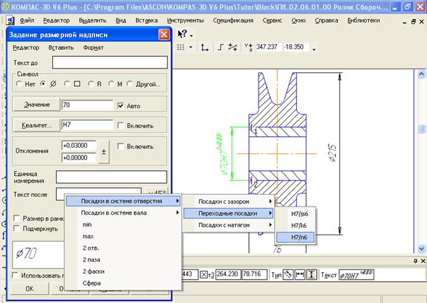
Fig. 6.5. Item popup menu Transient landing
click on landing H7 / n6 in the third popup menu. The selected fit is added to the dialog box. Set dimension text in the preview window;
Click the button OK in the dialog box Set dimension text;
Click the button Create object. The size set in the dialog box will appear in the dimension text box;
Click on the drawing field to deselect the newly edited size of the roller hole.
Fifth stage - setting of symbols for the roller and sleeve. For this:
Click on the toolbar View by button show all - the penultimate, with the image format;
Click the switch button on the Compact Panel. Legendand then on the toolbar that appears - click on the button Position Designation. The corresponding properties panel with two tabs will appear: Mark and Options;
Click the tab Options and set the parameters in it, as shown in Fig. 6.6.
Tab Sign there are two double fields for determining the starting point of the branch pointed to by the leader and the point where the shelf starts. When specifying points with the mouse, their coordinates are determined automatically and entered into these fields. The third field is Text - brings up a dialog box Enter textin which you can enter the desired inscription.
Tab Options there is a list Arrow, allowing you to select the type of arrow for marking, marking or positional callout markings.

Fig. 6.6. Setting the item number
There is also a switch Text down / up, allowing you to choose the direction of adding shelves of the positional leader line: down or up.
The last option is Default. When enabled, all current tab settings Options will be used when creating the following objects of the following type until the end of the session. When the option is disabled, the setting applies only to the current (created) object.
Click on the toolbar Current state by button Setting global bindings. A corresponding dialog box will appear;
Click the checkbox All bindings, if installed, to temporarily remove all bindings. They can interfere with the installation of position symbols, or rather the starting points of the positions;
Click the roller at the starting point of the extension line, then move the mouse pointer to the location of the extension line shelf and click;
Click the button Create object on the special control panel. The position label for the clip appears;
Click on the bushing at the installation point of the leader line, then move the mouse pointer to the location of the leader line shelf and click. The position number for the sleeve appears; click the button Create object on the special control panel. The position number for the sleeve appears.
The assembly drawing should contain: an image of the assembly unit; dimensions that must be made and controlled according to this drawing; instructions on necessary modifications during assembly, if only such modifications can meet the design requirements; item numbers of the component parts included in the pictured product.
Assembly drawing is used in the preparation of production and assembly of the product. The images on the assembly drawings should not only contribute to high-quality execution of assembly operations, but also give the opportunity to graphically check the correctness of the nominal values of the dimensions indicated on the drawings of the parts. Therefore, in the design offices, an assembly drawing of the product is performed by a draftsman who did not draw the drawings of the parts that are part of the assembly unit being depicted, which eliminates the work “from memory”. An accuracy check is performed by calculating the dimension chains to any desired decimal place.
At the end of the design stage, the resulting general view drawing is necessarily produced (code of the VO document). It contains an image of the product, on which the constituent parts are reflected as they are at the completion of this stage. The degree of preliminary study of the drawing depends on the qualifications of the detail masters and the capabilities of the lead designer (developer) of the product. In the general view drawing, typical elements of parts are not depicted, many components can be shown in a simplified and even arbitrary way. The number of images also depends on all the circumstances listed above.
A general view drawing is used when performing an assembly drawing (and not only at detailing) and when agreeing on the proposed construction.
General drawing, used in training conditions, is significantly different from production. Given the unpreparedness of junior students to self-design, it must contain as many images of the assembly as needed to fully determine the geometrical shape of literally every part of the product.
Images of typical parts, such as grooves, chamfers, may be missing or simplified in the drawing. We will return to this question in chapter 13, devoted to detailing.
The main standard relating to the topic of this subsection and the chapter as a whole is GOST 2.109 - 73 "Basic requirements for drawings."
9.3. Features of the image
The main image on an assembly drawing is almost always a slit, or it is a compound of a slit type, if a significant part of the product does not have components hidden from the observer, or the assembly unit contains the same groups of components (by analogy with a part drawing, assembly principle is widely used defaults in order to emphasize the uniformity of elements or parameters and reduce the drawing work).
If the drawing must contain two images, any of which can be taken as the main thing, the main thing is that which allows for a more rational layout of the drawing as a whole. 
Fig. 9.2. Permissible image of the scale and the arrow behind transparent glass
Fig. 9.1. Examples when the chamfer image determines the desired position of the part in the assembly unit
The total number of images of the product on the assembly drawing depends on the complexity of this product and the relative position of its component parts. There should be exactly as many images as needed to ensure the execution of assembly operations. In order to simplify the use of the drawing, local and partial images should be used wisely and remote elements should be used.
ESKD allows not to show chamfers, roundings, indentations, protrusions, corrugations and other small elements on the assembly drawings, if this does not interfere with the understanding of the drawing. The authors recommend that this assumption be widely used unless it is the listed elements that determine the position of the component parts in the assembly unit. Thus, the image of the chamfer on the sleeve (Fig. 9.1) determines the position of the latter in the body. Note that the absence of the image of the gap and annular undercut in Fig. 9.1, 5 also does not interfere with the understanding of the drawing.
Products made of transparent materials on assembly drawings are depicted as opaque. At the same time, the internal device of the lamps, scales and arrows of the devices can be shown as visible, despite the presence of protective glasses (Fig. 9.2). Thus, although there are no “transparent” materials for drawing, deviations from this rule are allowed when depicting some details. On a separate image, some component may not be depicted in order to “open” other invisible parts. In this case, the image is an inscription such as Det. pos. 24 conventionally not shown.
![]()
Fig. 9.3. Spring pictures:
but- full with a break;
b- sections of its turns;
at- in section;
g- when the thickness (diameter) of the cross section in the drawing is 2 mm or less
In fig. 9.3 shows various images of springs. Products located behind the coil spring, shown only by sections of the coils, are depicted up to the zone bounded by the axial lines of the sections of the coils (Fig. 9.3, b). If the spring is shown completely, the images of its turns overlap the images of the elements behind it. The image of a spring with a tearing out makes the elements visible at the point of tearing out (fig. 9.3, a).
On the cuts, the components for which stand-alone drawings have been drawn up, or which are typical, purchased, and widely distributed, are shown undifferentiated. Their image is limited to external contours without harm to the understanding of the drawing.
Topic 9. Basics of detail drawings
9.1. Assignment of drawings of parts and requirements for them
A drawing of a part is an image of a part, on which all dimensions necessary for its manufacture and control are applied, data on the material, surface roughness and technical requirements are indicated.
The detail on the working drawing is usually depicted in its final form, that is, the way it should go to the assembly. According to such drawings, the entire technological process of manufacturing a part is developed and flowcharts are drawn up, which depict the shape of the part at intermediate stages of manufacture.
In modern production in the manufacture of every detail involved employees of various professions. Each production worker, while reading the same drawing, finds out in him what he needs and determines his participation in the manufacture of the part. For example, before making a simple part from a sheet material, the process engineer and the worker according to the drawing establish the most rational cutting of the material, determine the ways to save it, set the marking sequence, etc.
Starting to manufacture a specific part of the drawing, it is necessary to decide how best to use the equipment, machine and tool, to organize the workplace. Sometimes it is better to make a device or a special tool to speed up the process of manufacturing parts and improve its quality.
A worker who can read drawings can make useful amendments to the technological process of manufacturing a part, to a snap (stamps, accessories, etc.), achieving material savings, improving quality, workability of the part and increasing productivity.
The quality of each production drawing is evaluated according to how it meets the requirements of production. General production requirements for drawing details, such as turned, cast, curved, etc., are as follows:
- in the drawing, the detail should be depicted in the minimum, but sufficient for clarification of the form, the number of species, sections and sections, using only such conventional images that are set by the standards;
- in the drawing, the roughness of the surfaces of the part should be indicated and all the required dimensions should be applied geometrically fully and structurally correctly;
- the drawing must contain the necessary technical requirements, reflecting the features of the part: the material and its properties, coating, dimensional deviations, tolerances of the shape and location of surfaces, etc.
Thus, the first basic requirement relates to the shape of the part, the second is related to the setting and dimensioning, the third to the technical requirements.
The purpose of drawing details as the most important production document, according to which parts are manufactured in production, imposes great responsibility on the designer. The speed and accuracy of its reading depend on how the drawing is drawn up and drawn up.
The requirements discussed are common to detail drawings. What should be the products themselves, for example, the details displayed on these drawings, and how should the drawing be associated with technology? How to ensure the reuse of drawings of the most successful, structural and technological parts and assembly units in the design of new machines?
These issues are now becoming of great importance in connection with the design of new machines and the introduction of new technology in all sectors of the national economy. They should be solved by an engineer when designing products and making drawings, but workers, technologists, all those who manufacture products according to drawings make a great contribution to this matter.
High culture of drawing provides:
- ensuring, in accordance with the requirements of production, the clarity and readability of the drawing at all stages of the manufacture of a product on it with the least expenditure of time on its reading;
- the lowest labor costs for the implementation of the drawing. This primarily concerns the rational display on the drawing of the form of the part, all its elements - the choice of the main image, the number of images, their relative position;
- correct, creative and complete (not formal) application of the standardization system in the drawing business and its subsequent achievements;
- use of elements of design and technology, analysis of the constructiveness and manufacturability of the part form in the initial drawing, making reasonable and consistent corrections;
- material savings (savings reserves are most often found when analyzing the overall dimensions); it is necessary to correctly set or determine the most advantageous overall dimensions according to the drawing with simple, widely available means, as well as other parameters of the part contours for the formation of optimal blanks and optimal cutting schemes;
- reasonable and economical choice of the format of the drawing and the entire layout of the images in the drawing.
High culture of the drawing is also inconceivable without a good graphic design technique of the drawing by the designer (inscriptions, signs, symbols, lines of the drawing - according to the relevant State Standards ESKD). The highest quality of manufacturing the drawing is achieved by the automation of engineering and graphic works, using computer-aided design systems:
“Low level” - AutoCAD, MiniCAD, KOMPAS;
"Intermediate level" - MechanicalDesktop, SolidWorks 96;
“High level” - Pro / ENGINEER, T-FLEX CAD, SPRUT.