General information about drawing execution rules
All the rules for the implementation of the drawings, currently in force, are reflected in the state standards (GOST) of the Unified System for Design Documentation (ESKD), which takes into account many recommendations of international standards organizations.
All standards provided by ESKD are distributed according to the following classification groups:
0 - general provisions;
1 - the main provisions;
2 - classification and designation of products in design documents;
3 - general rules for the implementation of drawings;
4 - the rules for the implementation of drawings in engineering and instrument making;
5 - rules for the circulation of design documents (accounting, storage, duplication, modification);
6 - the rules for the performance of maintenance and repair documentation;
7 - rules for the execution of schemes;
8 - rules for the implementation of building documents and shipbuilding documents;
9 - other standards.
In ESKD all standards have a certain structure of designations and names. For example, GOST 2.303-68 "Lines" means that the standard is included in the complex ESKD, which is assigned the number 2, the number of the standard is 303 (3 is the cipher of the classification group, 03 is the ordinal number of the standard in the group), the year of registration is 1968, "Lines".
It is quite understandable that all ESKD standards are developed for the industry and do not take into account the specifics of making drawings for other industries, therefore, when making such drawings, some deviations from the standards are allowed. When carrying out drawings, it is necessary to be guided by the requirements established by the "Unified system of design documentation", to formats, main inscriptions, scales, lines, fonts,
Formats of sheets of paper for drawings
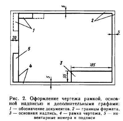
All drawings must be made on sheets of standard paper. The sizes of the sheets of paper are determined by the dimensions of the outer frame of the drawing (Fig. 1). It is carried out by a continuous thin line. The line of the drawing frame is drawn by a solid thick main line at a distance of 5 mm from the outer frame. On the left for the filing leave a field width of 20 mm. The designation and dimensions of the sides of formats are established in GOST 2.304-68. Data on the main formats are given in Table. 1.
Table 1
Format designation / Sheet side dimensions, mm
A1 / 594 x 841
A2 / 594 x 420
А4 / 297 х 210
The main formats are obtained from the AO format by successively dividing into two equal parts parallel to the smaller side. If necessary, it is allowed to use A5 format with dimensions of sides 148 x 210 mm. It is also possible to use additional formats. They are formed by increasing the sides of the main formats by an amount that is a multiple of the sizes of the sides of the A4 format.
The following deviations of the sides of the format are possible with dimensions of sides: up to 150 ± 1,5, from 150 to 600 ± 2,0, more than 600 ± 3,0.
The main inscription of the drawing
The main inscription of the drawing is located in the lower right corner of the format (see Figure 1). The form, dimensions and contents of the graphs of the main inscription are established in GOST 2.104-68. In the main inscription indicate: in column 1 - the name of the product; in column 2 - designation of the drawing; in column 3 - the material of the part; in column 4 - the name of the manufacturer of the drawing.
In the upper left corner of the drawing, in the 14x70 frame, the drawing designation given in box 2 of the title block frame, rotated by 180 °, is recorded.
On the A4 format, the main inscription is located only along its short side.
On formats larger than A4, the title block can be located on both the short and long sides. When the main label is positioned along the short side, the rotated drawing designation is located in the upper right corner along the long side.
see also
Scale of drawings
The image of the object in the drawing can be made in full size, reduced or enlarged.
Scaleis the ratio of all linear dimensions of the image of the object in the drawing to their natural value.
GOST 2.302-68 sets the following series of scales of images in the drawings:
scales of reduction -1: 2; 1: 2.5; 1: 4; 1: 5; 1: 10; 1:15; 1:20; 1:25; 1: 40; 1: 75; 1: 100; 1: 200;
the natural value is 1: 1;
scale of increase - 2: 1; 2.5: 1; 4: 1; 5: 1; 10: 1; 40: 1; 50: 1; 100: 1;
The image of the object on the drawing in the scale of magnification or reduction does not provide for the purposes of determining its dimensions, it is caused only by the need for correct visual perception of the shape of the imaged subject, therefore, regardless of the scale of the image, the dimensions on the drawing are displayed real.

The scale in the main caption of the drawing is denoted by type 1: 1; 1: 2; 2: 1, etc. The scale of the image, which differs from the one indicated in the title block of the drawing, is indicated immediately after the inscription relating to this image, according to the type: A (1:10), A-A (2: 5).
Drawing Lines
The main elements of any drawing are lines. Images of objects in the drawing represent a combination of different types of lines.
When drawing drawings, lines of different thickness and shape are used. Each of them has its own purpose. The thickness of lines of the same type should be the same for all images in this drawing.
GOST 2303-80 establishes the inscriptions and the main purposes of lines on drawings of all industries.
Inscriptions on the drawings
All the inscriptions in the drawings must be executed in the standard drawing font. A drawing font is also used for making inscriptions on other technical documents. In this case, letters of the font, numbers, individual inscriptions and text are executed by hand. Individual inscriptions can consist of only uppercase letters. The figures found in the text are also satisfied by a height equal to the height of the uppercase letters.
All inscriptions and dimensional numbers in the drawings must be clear and clear. The inscriptions are made with the fonts provided for in GOST 2.304-81 "Drawing fonts". These fonts include Russian, Latin and Greek alphabets, as well as Arabic and Roman numerals.
The standard sets the following font sizes: (1.8); 2.5; 3.5; 5; 7; 10; 14; 20; 28; 40. The font size h determines the height of uppercase (capital) letters and numbers in millimeters.
The thickness (d) of the font line is determined depending on the font height. It is equal to 0.1 h. The width (e) of the letters is chosen to be 0.6 h or 6 d. The width of the letters A, M, M, F, X, L, L, L, N, Y is greater than this value by 1 or 2d (including the lower and upper elements), and the width of the letters T, 3, C is less by d.
The standard sets the following two types of font depending on the thickness d of the font lines: type A (d = 1 / 14h) without inclination and with a slope of about 75 ° to the horizontal line; type B (d = 1 / 10h) without inclination and with a slope of 75 °. In Fig. 6 shows the form of the letters of the Russian alphabet and Arabic numerals, made in type B without inclination.
The minimum distance between words separated by a punctuation mark is the distance between the punctuation mark and the word following it.
When executing the inscriptions in the drawings with standard fonts, the distance a between the letters, the connection of lines that are not parallel to each other (for example, G and A, A and T, etc.) is reduced by half, that is, by the thickness of the platelets of the font. For all text, the thickness of lines of the same font should be the same.
Executed drawings often have a large number of alphabetic and digital inscriptions. As a rule, they should be placed horizontally. Avoid placing inscriptions inside the contour of projections (except for dimensional numbers). If the inscription is placed under the line or underlined by a line, then it should be about 1 mm from it.
If the inscription crosses the line, then at the intersection point the line must be interrupted. When completing the title block graph and other graphic documents, the inscription should be placed as far as possible from the lines bounding the graph.
Names, titles, labels in the title block, on the drawing field are allowed to be written without tilt. For fast execution of inscriptions by a drawing font sometimes use various stencils.
Dimensioning on a drawing
According to the images of the object in the drawing, it is judged on its magnitude and the magnitude of its individual parts. The basis for this is the dimensional numbers, regardless of the scale and precision with which the images are performed. The rules for drawing dimensions on the drawings are established in GOST 2.307-68.
Dimensions in the drawing indicate the dimensional numbers, dimension lines and extension lines. The dimensional numbers in the drawings, as a rule, indicate in millimeters without indicating the units of measurement. In cases where it is necessary to use other length units, they are shown after the dimensional number.
Dimension numbers are applied over a dimension line, possibly closer to its middle. The clearance between the dimension number and the dimension line should be about 1.0 mm. The height of the digits of the dimensional numbers is at least 3.5 mm.
The dimension line is parallel to the segment, the size of which is applied above it. It is carried out between the extension lines drawn perpendicular to the dimensional lines. It is allowed to draw dimension lines directly to the lines of the visible contour, axial and centric. In some cases, the dimension line may not be perpendicular to the outline line. Dimension lines restrict arrows. In some cases, they are carried out not completely, but with a broken arrow on one side. The size of the arrow is selected from the thickness of the continuous thick main line adopted in the drawing. Within the limits of one drawing the size of the arrows should be the same as possible. It is not recommended to use contour, axial, center and extension lines as dimension lines.
If the length of the dimension line is small to accommodate the arrows, then the dimension line is continued beyond the extension lines.
The remote lines are drawn from the measurement boundaries, they are auxiliary and serve to place dimensional lines between them. The extension lines should, if possible, be located outside the image contour, perpendicular to the straight line segment, the size of which should be indicated. The extension lines should extend beyond the ends of the arrows of the dimensional lines by 1 ... 5 mm.
The minimum distance from the dimension line to the line parallel to it should be 10 mm, and between parallel dimensional lines - 7 mm.
The angular dimensions in the drawings are indicated in degrees, minutes and seconds, indicating the units of measurement. The size of the angle is applied over the dimension line, which is carried out in the form of an arc with the center at its apex. Remote lines in this case are carried out radially.
If there is not enough room for writing a dimension number over a dimension line or this place is occupied by other elements of the image and a dimensional number can not be entered into it, the dimensional number is plotted according to one of the variants shown in Fig. below.

In order to simplify a number of images, create convenience for reading a drawing, the standard provides for the use of symbols in the form of letters of the Latin alphabet and graphic signs that are placed before the dimensional numbers. In the drawings, signs and letters are used to denote the diameter and radius, the length of the arc and the square, the slope and taper, the sphere, the thickness and the length of the part.
Before the dimensional diameter number, a circle is marked, crossed by a straight line at an angle of 75 °. Moreover, there are no omissions between the sign and the number.

For circles of small diameter, the dimensional lines of the arrow and the size itself are plotted according to one of the variants shown in Fig. below.


Before the dimensional number of the radius of the arc, a sign is always put in the form of a capital Latin letter R. The dimension line in this case is drawn towards the center of the arc and limited to only one arrow resting on the arc or its continuation. If the radius value in the drawing is less than 6 mm, the arrow is recommended to be placed on the outside of the arc.
If it is necessary to set the position of the center of the arc, it is marked by the intersection of the center or outline lines. In those cases when the drawing shows an arc with a large radius, for which the center can be omitted, the dimension line is cut off, not leading to the center. If, in this case, the center is to be noted, it is permissible to bring it closer to the arc. The dimension line in this case is shown with a kink of 90 °, and both sections of the dimension line are run in parallel. Do not place on a straight line dimensional lines that come out of one center and are intended to indicate dimensional arcs. Radii are recommended to designate arcs up to 180 °; The arcs, whose value is more than 180 °, are denoted by a diameter.
An arc is applied over the dimensional number. The length of the arc is set in linear units, and the dimensional number denoting the arc is applied over the dimension line in accordance with the usual requirements.
Designations of materials in the drawings.
The graphic indication in the drawing of the plotted object / article of the material gives us a necessary idea of the material (s) from which the object / product / part is made.
The designations of graphic materials and the rules for drawing them on drawings must comply with GOST 2.306-68.
When performing graphic material symbols, combinations of different types of lines are used, but always parallel lines drawn at an angle of 45 degrees to the center line or to the line of the drawing frame.
If the hatching lines coincide in direction with the contour lines or axial lines, then the hatch lines can be drawn at an angle of 30 or 60.
The distance between the lines of hatching should be 1-10 mm, taking into account the area of hatching and the need to diversify the hatching of adjacent areas.
Hatch lines can be tilted to the right or left, but one side on all sections and sections related to one element in this drawing.
The thickness of the lines and their outline are taken in accordance with GOST 2.303-68 *.
If the parts are adjacent, then for one part the lines of hatching are tilted to the right, for the other to the left (counter hatching).
When hatching into a cell, in such cases, the distance between the lines of hatching in one section should differ from the corresponding distance in the other.
If three different parts touch each other, you should change the distance between the lines in the hatching or shift these lines in one section with respect to the other, without changing the angle of their slope.
Narrow and long sections of sections, the width of which in the figure is 2-4 mm, it is recommended to hatch completely only at the ends and contours of the holes, and the rest of the sectional area - hatch only in small areas in several places.
Narrow areas, the width of which is less than 2 mm, may be shown blackened with gaps of not less than 0.8 mm between adjacent sections.
When depicting the soil profile and large areas of sections, it is allowed to apply the notation in the form of a narrow band of uniform width only at the contour of the section.
To clarify the variety of the same type of materials, the graphic designation should be accompanied by an explanatory inscription on the drawing field.
Shading of the cross-sections of building structures without graphic designation of materials is allowed.
General information. General rules for the execution and reading of drawings are laid down in the state standards of the ESKD of the 3rd group and the 2nd group SPDS, which establish drawing sheet formats, scales, line types, headset and font sizes, rules for constructing images (types, sections, sections) graphic materials and the rules for their application in drawings, the rules for drawing sizes and inscriptions, the construction of axonometric projections (concrete designations of the state standards of ESKD and SPDS, which will be required in solving problems of control are listed in the instructions for the implementation of the sheets).
Theoretical and practical mastery of the position of the standards of these groups contributes to the formation of the student's initial engineering graphics, without which it is impossible to proceed to the successful study of specific features of building drawings of building products and structures, as well as the geometric and graphic foundations of modern computer graphics.
At the base of any graphic representation presented on the drawing field (alphanumeric designation, inscriptions, drawing frame, title block, kinds of parts, dimensional lines and numbers to them, etc.) lies a speci fi cally defined or fixed thin line in the drawing the sequence of geometric constructions, the result of which is formalized in strict accordance with the above state standards of ESKD and SPDS. In this regard, the student is required to consistently and accurately perform all the geometrical constructions, connected both with the drawing up of the drawing, and with the construction of the species, the depicted objects or their elements, in a thin line.
Instructions for performing tasks. Dimensioning is carried out according to GOST 21.105-79 and 2.307-68. The total number of dimensions in the drawing must be minimal, but sufficient for the manufacture and control of the product. The linear dimensions are in millimeters. Dimensions on the drawings indicate dimensional numbers and dimensional lines.
The dimension line at both ends is limited by serifs in the form of thick basic lines 2-4 mm in length, inclined to the right at an angle of 45 ° to the dimension line (Figure 3, a).The dimensional lines of the radii of the arcs and the diameters of the circles are bounded by arrows.
Dimension lines are preferably applied outside the image contour. The extension lines should extend beyond the dimensional lines by 1 ... 3 mm. The minimum distances between the parallel dimension lines must be 7 mm, between the dimensional and the contour line - 10 mm and are selected depending on the image size and the saturation of the drawing. Dimension numbers are applied over a dimension line at a distance of not less than 1 mm and possibly closer to its middle. It is necessary to avoid crossing dimensional and extension lines. Dimensions related to the same structural element (groove, ledge, hole, etc.) are recommended to be grouped in one place, placing them in the image on which the geometric shape of this element is shown most fully.
When the size of the radius or diameter is applied before the dimensional number, the uppercase letter Ror the Ø sign (Figure 4). When you display a part in one projection, the size of its thickness (length) is placed on the shelf of the leader line and before its value is placed the lowercase letter s ( l).
When tracing a drawing, it is necessary to strictly adhere to the requirements of GOST 2.303- 68 *, which regulate the outline and the main purposes of lines in the drawings.
Figure 3. Designation of dimensional lines.
Figure 4. The designation of the application of the size of the radius or diameter.
SHEET 1
Format A3. The main inscription on the form 4a. Perform two tasks for building conjugations and biases, as well as for acquiring skills on the outline of circular curves. For an example of a sheet, see Fig. 6.
Figure 5.
Table 1.
Table 2.
Figure 6. An example of a sheet.
Task 1. Construct conjugations of three circles with the help of a straight line and two arcs of circles (internal or external). The initial data is taken from Fig. 5 and tab. 1.
All graphic procedures of step-by-step construction of interfaces on the drawing must be preserved. Make the task in accordance with Table. 2. In Fig. 7 shows examples of conjugation of two circles: a- external conjugation by an arc of a circle of radius r 2; b-external conjugation of a straight line; c is the inner conjugation by an arc of a circle of radius r 1.
Figure 7. Examples of conjugation of two circles: a- internal conjugation by an arc of a circle of radius r 2; b-external, conjugation of a straight line; at- inner conjugation by an arc of a circle of radius r 1.
Task 2.Construct the matings and slopes of the shelves on the rolling steel profile - I-beam or channel - at a scale of 1: 1. Individual tasks are shown in Fig. 8 and in Table. 3.
Figure 8. Individual tasks.
When constructing the profiles of the I-beam and the channel, all dimensions are taken from Table. 3. To reduce the profile image height, a vertical wall rupture is applied. In the drawing, instead of letter designations, the dimensional numbers calculated by the indicated relations of Fig. 6. The geometrical diagram of the slope, the conditional graphical designation of the profile and the extended remote node 1 are executed.
When drawing the drawing, comply with the requirements of state standards for line types and rules for dimensioning.
Table 3.
SHEET 2
Format A3. The basic inscription on the form 4. To execute the task on construction of the basic kinds of a detail. For an example of drawing a sheet and assigning it to it, see Fig. 9, 10.
Figure 9.An example of a sheet.
Figure 10.Task for the task of building the main types of parts.
A task.According to the given axonometric image of the detail, there are six main types. Individual tasks are listed in the following table. 4.
In accordance with GOST 2.305-2008 set the main types of parts. Pay special attention to the choice of the main view (front view). Dimensions on the images do not show.
Table 4.
SHEET 3
Format A3. The basic inscription on the form 4a, To execute two tasks on construction of kinds, cuts and sections of a detail. For an example of a sheet, see Fig. eleven.
Figure 11.An example of a sheet.
A task1. Construct three kinds of parts (front view, top view, left view) with the necessary cuts for these two types. Individual tasks on the options are shown in Table. 5.
Instructions for completing the task 1. To study the content of GOST 2.305-2008, drawing attention to the conventions and simplifications adopted in it. Part of the species and part of the corresponding section are allowed to be joined, separated by a continuous wavy line. If in this case half the species and half of the cut are joined, each of which is a symmetrical figure, then the separating line is the axis of symmetry. If a view, cut or section represents a symmetrical figure, it is allowed to draw half the image or slightly more than half the image with the break line in the latter case. Apply the image to the image.
Task 2.From the given position of the secant plane, construct the section of the part. The position of the cutting plane is indicated in the individual task.
Instructions for the task 2.Section construction is performed in strict accordance with the rules for constructing projections in descriptive geometry, and design - in accordance with GOST 2.305-2008. The cross-section is located on the free field of the sheet. The contour of the remote section is represented by solid main lines. The section plane is hatched. Section is accompanied by an inscription on the type "1-1", "A-A". The font number of the inscription is twice as large as the font number adopted for the dimensional numbers in this drawing.
Table 5.
SHEET 4
Format A4. The basic inscription on the form 2. To execute a task on construction of an axonometric image of a detail.
A task.For two kinds of details, construct its axonometric projection with cuts. The initial data is taken from Table. 5.
Specifyingto the task.GOST 2.317-2011 recommends five types of visual images: rectangular isometry, rectangular dimetry, oblique frontal isometry and dimetry and oblique horizontal isometry. The type of axonometric projections is chosen depending on the form of the objects being represented. One of the characteristic points of the object can be taken as the origin of coordinates. The object can be included in the parallelepiped and carry out the construction of axonometry, making readings from its faces. In Fig. 13 shows the angles between axonometric axes, as well as the direction of the axes of ellipses that are projections of circles (parallel to planes XOY, XOZ, YOZ ),
Figure 12. An example of a sheet.
Figure 13. Angles between axonometric axes, as well as the direction of the axes of ellipses, which are projections of circles (parallel to planes XOY, XOZ, YOZ ).
Ellipses in order to facilitate the construction can be replaced by ovals consisting of arcs of circles drawn from four centers. In rectangular isometry for the construction of ovals, the centers O 1 and O 2 determine a size equal to half the major axis of the ellipse, and the centers O 3 and O 4; - the size equal to half of a minor axis.
In rectangular and oblique-angled dimers, when constructing an oval that replaces ellipses 1 and 3 , the centers O 1 and O 2 are located from the point It is the distance of the major axis of the ellipse. The centers O 3 and O 4 are located from the points A and B of the major axis of the ellipse at a distance equal to the fourth part of the minor axis of the ellipse.
The centers O 1, O 2, O 3, and O 4 of the oval arcs replacing the ellipse 2c in the rectangular dimen- sion are at the intersection points of the horizontal lines drawn from the points M and N (the line MN is parallel to the axis OX ), with the axis of the oval of the AI and the axis C 1 D 1 of the ellipse.
In the axonometry sections are performed by two (or more) secant planes. To draw a cut of an object, you first need to build its axonometric image, and then outline the lines along which it is dissected by a plane. The direction of the hatching lines is taken in parallel to the diagonals of the faces of the cube, which are respectively parallel to the planes XOY, XOZ, YOZ
All the lines of construction to save, otherwise the sheet will not be credited. In the drawing, the selected position of the axonometric axes with the angles between them is displayed in the free space. If the imaging object has internal cavities, a cut must be made.
The problem is that, having orthogonal projections of a certain detail (Figure 14, a)imagine the three-dimensional shape of this part in any given position and then visually in the axonometry to represent it by hand (Fig. 14, d. is made in rectangular isometry).
The stages of constructing the form of a technical detail are clear from the figure. First, axonometric axes coinciding with the axes of symmetry of the part are marked, then the axis of the holes and the main dimensions of the upper part of the part are marked (Figure 14.6). Later on, the thickness of the lid is revealed and a cylindrical part of the part is built, a cut is made (Fig. 14c).
Figure 14.Stages of building a form of technical detail.
Questions for Knowledge Control
To topic 1 "Drawing standards".1. What is standardization, standard? 2. What are the categories of standards? 3. What is ESKD? 4. What is SPDS? 5. How to organize a workplace? 6. How are basic formats formed and denoted? 7. What are the sizes of formats A3 and A4? 8. At what distance from the edge of the format is the frame of the drawing, what lines? 9. How do they have the main inscription on A4, A3? 10. What is the purpose of the drawing lines? 11. What types of fonts does GOST 2.304-81? 12. What is the font size? 13. What is the difference between lowercase and uppercase? 14. What is the ratio of the width of the letter, the thickness of the font line and its height? 15. What is called scale? 16. What are the standard scales and the number of the corresponding GOST? 17. At what distance should the dimensional lines be drawn from the contour lines and between the parallel dimensional lines?
To theme 2 "Geometric constructions".1. What is bias? 2. How to construct the conjugation of two circles? 3. What is the taper? 4. How to build mates and slopes of shelves on the profile of rolled steel: a) I-beam; b) Channel Channel? 5. How to construct internal conjugation of circles by an arc of a given radius?
Go to topic 3 "Images".1. What is the detail view? 2. What kinds do you know? 3. What is a cut? 4. What is a complex cut? 5. What is a section? 6. What kinds of axonometric projections do you know? 7. What are the angles between axonometric axes in rectangular isometry (dimetry)? 8. How do technical drawings?
Part II
Drawings of products
General information about the performance of product drawings. Working drawings of products are made in accordance with GOST 2.101-68 (ST SEV 364-76), 2.102-68 *. 2.109-73, and drawings of construction products also taking into account the additional requirements of the 3rd section of GOST 21.101-97. Working drawings of construction and engineering products have differences in the design of dimensional lines, shapes and fillings of the main inscriptions, the placement of specifications and rules for the execution of drawings of simple details, etc.
Types of products. An item is any object or set of items of production that are to be manufactured in the enterprise. Construction products are to be manufactured at the enterprises of the construction industry and are intended for the erection of buildings or structures. In some cases, some products in single copies can be produced directly on the construction site, but not at the site of assembly of prefabricated structures, or at the site of production.
The following types of products are installed: parts, assembly units, complexes and kits. Figure 15 shows the scheme of dividing the product into its component parts.
Figure 15. Scheme of division of the product into its component parts.
Detail - a product made of a single grade material without the use of assembly operations. In the manufacture of parts, you can use local welding, gluing, stitching, pressing, casting. As a rule, parts are used in the form of component parts of the assembly unit, for example, rods, loops of reinforced concrete products - slabs, etc.
Assembly Unit -the product, the constituent parts of which are to be connected to each other at the manufacturing plant by assembly operations. The overwhelming number of building products - assembly units: all prefabricated reinforced-concrete and joinery products (except plinths, platbands, etc., which are parts or material), metal ladders, fences, etc. In the assembly units, in turn, other assembly units may be included (for example, an assembly unit whose spatial framework consists of mesh assembly assemblies, frameworks, embedded products), as well as parts such as individual rods, hinges, standard products, materials. To the assembly units, if necessary, also include a set of items jointly installed at the manufacturer.
Complex - Several products (assembly units, parts) not assembled at the manufacturing plant by assembly operations, but designed to perform interrelated operational functions. For example, a set of assembly units, parts and standard products of a sanitary or kitchen unit assembled at a construction site
Set - two (or more) products not connected at the manufacturing plant by assembly operations having a general operational purpose of ancillary nature, for example, a set of instrumentation for the automation of sanitary systems, cookers, etc.
Sheet 5
Format A3.Basic inscription on the form 46. Complete four tasks for the image of detachable and one-piece connections. For an example of a sheet, see Fig. 16.
Figure 16. Example of design.
Task 1. Construct a bolted connection. The scheme of the task is shown in Fig. 17, and the numeric data in Table 6.
Table 6.
Figure 17. Workflow
Instructions for completing the task 1. The geometrical diagram of the connection is shown in Fig. 18. Images of the connected parts must be of the same dimensions as in the figure relating to the variant of the job. The diameter of the rod of fasteners is determined by the size of their thread.
In the course of the task, it is necessary to choose the bolt dimensions according to GOST 7798-90, according to which the length of the bolt from 20 to 80 mm is a multiple of 5 mm, and from 80 mm and more is a multiple of 10 mm.
Drawing of bolted connections should be plotted according to the conditional relations shown in Fig. 16. Calculation of the bolt size is carried out on a separate sheet in a box, which is glued to the right end of the sheet.
For the bolted connection, a simplified and conditional image is also drawn. Simplified image in a scale of 1: 4.
Figure 18.Geometrical connection scheme.
Task 2. Construct a pipe connection. The scheme of the task is shown in Figure 19, the numerical data in Table 7.
Table 7.

Figure 19. The scheme of the task.
Task 3. To depict the conventional designation of the standard welded joint, using reference application 1 of GOST 2.312-72 and a table of variants of tasks (Table 10). Students who have odd number options, perform auxiliary signs for welds on the front side, and even - on the reverse side. The dimensions of the connected parts must be taken independently.
Instructions for the task 3. According to GOST 2.312-72, the seam of a welded joint, irrespective of the welding method, is conventionally represented: visible by a solid main line; invisible - dashed line.
From the image of the seam, draw a line, which ends with a one-sided arrow. Auxiliary signs for the designation of welds are given in Table. 8. In the symbol for the seam, the auxiliary signs are made with solid, thin lines. The auxiliary signs must be of the same height as the digits included in the designation of the seam.
The structure of the conventional notation for the standard joint is shown in Fig. 20, where 1 - auxiliary signs of the seam along the closed line and the installation seam; 2 - designation of the standard for the types and structural elements of the joints; 3 - alphanumeric designation of seams; 4 - conventional designation of the welding method; 5 - sign and size of the weld joint; 6 - characteristic of the weld or single welded point; 7 - auxiliary signs selected from Table 10. The designation of the seam is applied to the shelf of the leader line drawn from the seam image on the front side (Figure 21a) or under the shelf of the leader line drawn from the seam image from the back side (Fig. 21b).
Table 8.
Figure 20. Structure of conventional seam designation
Figure 21. Place of the seam designation
Figure 22. The main inscription.
SHEETS 6, 7, 8, 9
The complex work is carried out: the design of the reinforced concrete product drawing up of the specification, the assembly drawing, the drawing of the assembly unit and the details of the reinforced concrete product. Variants of the task are given in Table. 11 and in Fig. 23. In its variant, the student counts the number of rods and their length, taking into account the dimensions of the structure. The reinforcing welded mesh and the reinforcement are placed so that they have protective layers of concrete in 25 ... 30 mm - this prevents them from corrosion under the influence of the external environment. The depth of the nest under the column is h / 2.
When performing the work, pay special attention to the identity of the filling of the "Designation" graph in the specification and the main inscriptions to sheets 6. 7, 8. 9.
Figure 23. The task.
Sheet 6
Format A4. The basic inscription on the form 3. Solve the task of drawing up the specification.
Sheets 6 and 7 place on one sheet of A3 format. An example of a sheet is shown in Fig. 24.a.
A task. Specify the specification for the reinforced concrete product according to its variant in Table. 9 and Fig. 23.
Table 9.
Instructions for the task. The specifications of construction products comply with GOST 2.108-68 * (Figure 25). Such a sequence of drawing up sections of the specification is established: documentation, assembly units, parts, standard products, other products, materials. The names of the sections are indicated in the form of headings and underlined by a thin line. After each section, you must leave several free lines.
In our example, the sections for the specification of a reinforced concrete product (see Figure 24, a) contain: 1) "Documentation" - these guidelines and an assembly drawing of a reinforced concrete product; 2) "Assembly units" - assembly drawings of the component parts of the products (reinforcement mesh): 3) "Parts" - individual rods that are not included in the reinforcement mesh, as well as mounting loops; 4) "Material" - the concrete used in the product.
The columns of the specification are filled in as follows:
a) in the column "Format" indicate the formats of documents, the designation of which is written in the "Designation" column. For parts for which drawings have not been issued, the index is indicated in the graph of the CU index (without a drawing);
b) in the column "Zone" indicate the designation of the zone in which the position number of the recorded component part is located. The graph is filled only for drawings, broken into zones according to GOST 2.104-68;
c) in the column "Pos." indicate the serial number of the components directly entering the specified product. The column is not filled in for the "Documentation" section.
Figure 24 a. An example of a sheet.
Table 24, b. An example of a sheet.
d) in the column "Designation" indicate: in the "Documentation" section - the designation of these guidelines and the designation of the assembly drawing of the product, in the sections "Assembly units", "Details" - designation according to the drawings of the reinforcing mesh and the drawings of the rods and the mounting loop. The designation of the component part of the product in the specification is at the same time the designation of the design document (drawing), in which this component is depicted. It is advisable to designate the documents that make up the reinforced-concrete products on the subject system for constructing a designation, where the following interrelated types of documents and their designation are distinguished (Figure 26). The alphanumeric designation of the assembly drawings is accompanied by the SB index;
e) in the column "Name" indicate the name of the document or the name of the product. In this case, in the case without drawing information (i.e., for parts not having drawings), a record is made that is necessary and sufficient for the manufacture and control of this part, as follows:
rod Æ12 A-I GOST 5781-82 l = 1150;
e) in the column "Col." indicate for the components of the product their quantity per one specified product, in the "Materials" section - the total number of materials per one specified item, indicating the units of measurement. It is allowed to record units of measure in the "Note" column;
Figure 25. Specifications of construction products.
g) in the column "Note" indicate additional information for planning and organization of production, as well as other information related to the products recorded in the specification, documents, for example, for parts that are not issued drawings - mass. As a rule, the specification is carried out on a separate A4 sheet. The specification can be combined with an assembly drawing. The specification is located below the graphic image. Such a combined document is assigned the designation of the specification, i.e., without the SB index.
Figure 26. Interrelated types of documents and their designations.
SHEET 7
Format A4. The main inscription on the form 2. Solve the task for the implementation of the assembly drawing of the reinforced concrete product. An example of a sheet is shown in Fig. 24.6.
A task. Run on a scale of 1:10 or 1:20 an assembly drawing of a reinforced concrete foundation block according to its version in Table. 11 and in Fig. 23.
Instructions for the task. The assembly drawing must contain complete information about the location of the components and the way they are connected. Identify the shape and dimensions of the components, for which there are separate drawings, here it is not required, since the component parts are delivered to the assembly in finished form (welded mesh). The main view of the assembly unit - the component part of the structural element - must correspond to its intended position in the manufacturing process (assembly, welding, etc.). Long (tall) assembly units, including masts, columns, poles, can be placed horizontally on the drawing. In the simplest cases, the assembly drawing can consist of one type, if it does not cause difficulties when using it in an assembly operation, for example, a flat grid drawing, etc.
Types and cuts are given dimensions, instructions on the nature of the connection of components and other requirements that must be met and monitored in accordance with this drawing, as well as the necessary installation and attachment dimensions, the dimensions of individual parts for which the drawings do not produce. All parts of the product are numbered in accordance with the item numbers specified in the specification.
Number of positions in the drawing indicate, as a rule, once. Position numbers are placed on the shelves of the callout lines drawn from visible images, usually from the main views and cuts and placed outside the image contour. Reinforcement and embedded products are drawn up by independent drawings.
As a rule, do not apply the graphic designation (hatching) of the material in the cross-section when plotting the cuts. Reinforcement products are indicated by conventional and simplified images in accordance with GOST 21.107-78. The reinforcement scheme is carried out under the assumption of transparency of the concrete.
The reinforcement in the views and in the section should be encircled by a line 0.8 mm thick, the outline of the foundation that fell into the cross section is 0.6 mm, and not falling into the section - 0.4 mm; dimension and extension lines - 0.2 mm.
SHEET 8
Format А4. The basic inscription on the form 3. Two problems solve: drawing up of the working drawing of the assembly unit (reinforcing grid) and the grid of the specification combined with the assembly drawing.
Sheets 8 and 9 place on one sheet of A3 format. An example of a sheet is shown in Fig. 27, a.
Task 1. Write a specification to the assembly unit - reinforcement mesh - according to the variant of Table. 11 and Fig. 23.
Instructions for completing the task 1. Refer to the instructions for the task of sheet 6. The specification is located above the main label.
Task 2. Run the working drawing of the assembly unit - the reinforcing mesh.
Instructions for the task 2. Working drawings of reinforcing products: nets, frames, spatial frames, individual rods and loops are made in accordance with the rules of GOST 21.503-80. When mesh is displayed, rhythmically placed rods are applied at the ends of the row, as well as in the places where their step is changed. In this case, under each shelf line-callouts with the position number indicate the step of the rods. In the assembly drawings, the symbols of the welded joints are given in accordance with GOST 2.312-72. In this task, contact spot welding is used (GOST 14098-91-K1-KT). The rest can be found in the instructions given to the client 7.
SHEET 9
Format A5 (148X210 mm). The basic inscription on the form 2. To solve the task on drawing up of the working drawing of a detail. For an example of a sheet, see Fig. 27, b.
Task 1. Draw a working drawing of the assembly hinge part - according to the variant of Table 11 and Figure 23. The dimensions of the loop are taken according to the drawing in Fig. 27b.
Instructions for the task.In the project documentation, drawings of the details of the assembly units are not carried out if they are so simple that the data for their manufacture can be brought into the specification and (or) on the assembly drawing. If necessary, drawings of individual parts are performed in the free field of the assembly drawing (in our case, this could be done).
Figure 27, a. An example of a sheet.
Figure 27, b. An example of a sheet.
In the drawing, the details show its image, dimensions and other data necessary for manufacturing and control. In the main types, the part is shown as it arrives at the subsequent assembly. For symmetric parts, the symmetry axis is parallel to one of the sides of the drawing frame. Flat parts are represented in one projection describing their configuration.
SHEET 10.
Format A3. The basic inscription on the form 2. To execute tasks on drawing up of the drawing of the assembly of a building design. An example of registration is shown in Fig. 28.
A task. Draw a 1: 5 scale drawing of the welded truss farm assembly shown in Fig. 28, according to the variant of Table. 10.
Instructions for the task.When performing the work, it is necessary to study the content of the node specification (Figure 29) and the features of graphic design of the drawings of metal building products, set out in GOST 2.410-68, and also in GOST 2.312-72 and 2.315-68.
One of the main features of the execution of metal building products (building elements) of buildings (structures) is the system of location of the kinds of represented projections: top view in the projection connection - above the main view; view from below - under the main view; The right view is to the right of the main view; The left view is to the left of the main view; over each type (except the main one) make an inscription of type "A", and the direction of sight is indicated by an arrow indicated by the corresponding letter.
On the drawings of metal building products, a symbol is permitted and the dimensions of the material profile are indicated on the part images. Data about the profiles are applied in parallel to the images of the parts. It is allowed to put this data on the shelves of the leader lines. Dimensions of the profile or its number and length of the part are placed next to the symbol, to the right of it. The number of applied parts in the product shown in the drawing is indicated next to the dimensions of the part through the dash.
Details of metal building products are connected by welded seams, riveted or bolted connections, which also have their own specific symbols and execution rules.
Welded joints are performed on drawings according to the requirements of GOST 2.312-72. If there are identical seams in the drawings, the designation is applied to one of the images, and from the images of the remaining identical seams, draw lines with shelves.
Table 10.
All the same seams are assigned one ordinal number (Fig. 30).
In the images of metal structures and building products, welded joints are used for factory and welded assembly connections. In a graphic representation, these two types of connection differ only by one auxiliary sign ┐ placed at the intersection of the leader line and the leader-line flange in case of an assembly weld.
In addition to the auxiliary sign of the welded joint, it is necessary to repeat all the auxiliary signs regulated by GOST 2.312-72. In the work the student will need auxiliary signs:
Figure 28. Example of design.
Figure 29. Content of the site specification
All drawings must be carried out in accordance with the ESKD standards, and be clearly and accurately executed.
Formats
The drawings of the test work are carried out on standard size sheets. The standard sizes of sheet formats are defined in GOST 2.301-68. The sizes of formats on the outer frame are given in Table 1.
Dimensions of formats according to GOST 2.301-68 Table 1
|
Notation |
Size of the sides of the format, mm |
Test tasks should be performed in A4 and A3 format.
In accordance with GOST 2.301-68, the drawing has a frame at a distance from the left border of the format of 20 mm, from the other three sides at a distance of 5 mm (Fig. 1). The outer border of the format is made with a solid thin line, the inner frame is applied with a solid main line.
The field on the left side is for binding and stitching drawings into the album.
The drawing is accompanied by the main inscription according to GOST 2.104-68. On the A4 sheet, the main inscription is placed only along the short side
Fig. 1. Location of the main label on the sheet
The main inscription

Fig.2.a. Form of the main label

Fig.2.b. A sample of filling the title block of the UCH
|
Font size, mm |
||
|
Name of the drawing | ||
|
Designation of the document in accordance with GOST 2.201-80 | ||
|
Designation of the material of the product | ||
|
Drawing letter "y" training drawing | ||
|
Product Weight | ||
|
Order number of the sheet | ||
|
Total number of sheets | ||
|
Name of school and group code | ||
|
The nature of the work performed by the person signing the document | ||
|
Surnames of persons who signed the document | ||
|
Signatures of persons whose surnames are indicated in column 11 | ||
|
Date of signing the document | ||
|
Graphs of the change table |
Box 2: IG - the code of discipline,
851 - group number,
002 is the number of the variant,
001 - drawing number.
Box 9 of the VGKS is the name of the educational institution,
TE851 - 22 - group number and student code.
Scope
When drawing drawings, scales of images are used, which are selected from the following series in accordance with GOST 2.302-68:
scale reduction: 1: 2; 1: 2.5; 1: 4; 1: 5; 1:10; 1:15; 1:20; 1:25; 1:40; 1:50; 1:75; 1: 100; 1: 200; 1: 400; 1: 500; 1: 800; 1: 1000;
scale of increase: 2: 1; 2.5: 1; 4: 1; 5: 1; 10: 1; 20: 1; 40: 1; 50: 1; 100: 1.
The preferred scale for the training drawings is a scale of 1: 1 (full-size image).
In the main inscription in column 6 scale is entered as 1: 1 or 2: 1. In the drawings, it should be referred to as M 1: 1 or M 2: 1, etc.
Lines
The thickness of the lines must strictly comply with GOST 2.303-68. The name, outline, thickness of the lines in relation to the thickness of the main line and their main purposes are given in Table 3.
Drawing Lines Table 3

Work plan for the drawing:
Applying basic images in order to evenly fill the drawing field, all the lines are made thin so that they can be easily removed.
Then carry out the axis of symmetry, the center lines.
Draw the contour lines and draw individual image elements (grooves, holes, etc.).
The outline of the drawing is wide.
unnecessary lines that can not be traced are removed.
Using Lines in AutoCAD:
1 solid main thick (contour) - 0.60 mm;
2 - the main thin - 0.20 mm;
3 - axial (dash-dotted thin) - 0.25 mm;
4 - dashed (invisible contour) - 0.3 mm;
5 - dash-dotted thin with two points (fold lines on the reamer) -ACAD ISO 12W100 - 0.25 mm.
Font
All the inscriptions on the drawings and other technical documents of all industries and construction are carried out in standard type.
GOST 2.304-81 sets two types of font: type A and type B, with slope and no inclination. Figure 3 shows a type B.
It is recommended to study the design of writing font letters in alphabetical order, and divide them into groups according to the uniformity of the spelling. For a basis it is possible to take a principle of accommodation of elements of letters concerning an auxiliary grid which is shown on drawing 3 a.
In these guidelines, the font type B with a slope of 75º and the parameters given in Table 4 are considered in detail.
The font size h determines (in mm) the uppercase letters. The height of lowercase letters with (without appendages) is determined from the ratio of their height to the font size (for example, c = 7/10 h). In relation to the height of capital letters, all other font parameters are defined: g - width of the letter; d is the thickness of the font line (d = 1/10 h); a is the distance between letters; b - minimum line pitch (height of the auxiliary grid); e is the minimum distance between words.

Fig.3. Font type B with slope according to GOST 2.304-81

Fig.3.a Constructing type B font on auxiliary grid
Type B font parameters Table 4

Dimensioning
The value of the illustrated product and its elements in the drawings is determined by the dimensions, the total number of which should be minimal, but sufficient for manufacturing and its control. The linear dimensions are indicated in millimeters without the designation of units, in other units the dimensional number is accompanied by the designation of this unit. Angular dimensions indicate the drawing in degrees, minutes and seconds.
Rules for the application of dimensions are established in GOST 2.307-68. Dimensions on the drawings indicate dimensional lines. Dimension lines are limited by arrows that touch outline lines, contour lines, center lines. The extension line extends beyond the arrow by 1 to 5 mm. The dimension line is parallel to the segment, the size of which is indicated, if possible, outside the contour of the image. The minimum distance between parallel dimension lines is 7 - 10 mm, and between the dimension line and the contour line of 10 mm (they are selected depending on the image size and the saturation of the drawing). Dimensional lines should not intersect with remote lines.
Dimensions in the drawings are applied only on the visible elements of the product. The dimensions of invisible surfaces are allowed when these surfaces are not shown anywhere visible.
Some examples of dimensioning are shown in Figures 4 (a - 3).

a) The shape and size of the arrows

b) Rules for the application of dimensional lines

c) Application of angular dimensions

d) Dimensioning on flat drawings

e) Location of dimension lines


e) Dimensions of facets g) Signs of radius and diameter


h) Cases of breakage of a dimensional line and drawing of the sizes at a disadvantage of a place
Fig. 4a-4d. Rules for the application of dimensions in accordance with GOST 2.307-68
It is not allowed to use contour lines, axial, center, extension lines as dimensional lines. Each size is indicated only once. Dimension numbers are placed above the dimension line as close as possible to its center. To denote the diameter and radius, signs are placed in front of the dimensional number (see Fig. 4). Dimension line when indicating the magnitude of the angles is carried out in the form of an arc with the center at the apex of the angle (see Fig. 4c).
In the shaded area, the application size is not recommended. Dimensional numbers in this case indicate horizontal lines-shelves. It is not allowed to break the contour line for drawing a dimensional number, other lines are allowed. With parallel dimensional lines, the dimensional numbers are staggered. If there is not enough space for the arrow, lines near it are interrupted. Dimensional lines at different slopes determine the position of the dimensional numbers. In the presence of repeated elements indicate their number. The rules for indicating dimensions on the drawings are extensive, they should be studied in accordance with GOST 2.307-68.